
BP3 vs BP5 vs BP6: An Independent Pan Assembly Busbar Comparison
BP3 vs BP5 vs BP6: An Independent Pan Assembly Busbar Comparison
A pan assembly busbar is the pre-fabricated conductive assembly that replaces individual cable links inside a low-voltage distribution panel, carrying current from the incoming feed pillar to outgoing breaker terminals through fixed connection points. Because that geometry is fixed at the moment of order, choosing between a three-pole MCCB busbar, a two-pole MCCB busbar and an MCB busbar is a load-profile decision rather than a quality ranking.
This comparison examines three models from Barfuse (Yueqing Barfuse Electric Co., Ltd.), a Wenzhou-based manufacturer of low-voltage fuse switch disconnectors, busbar systems and distribution wiring management products including MCB and MCCB pan assemblies. The models are BP3 (MCCB 3P), BP5 (MCCB 2P) and BP6 (MCB). None of the three is universally superior; each maps to a different breaker family, current band and terminal geometry. What a buyer actually needs is a way to translate a project load profile into a purchase order that cannot be misread.
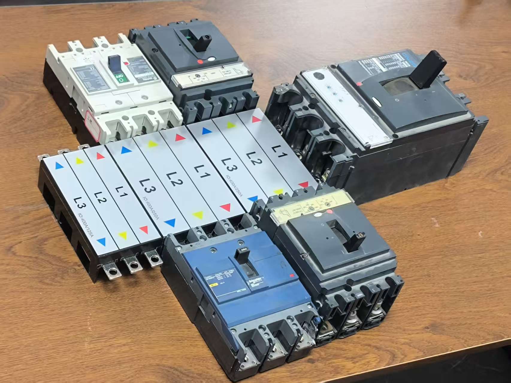
Figure 1 — An installed pan assembly busbar: the conductive spine between the incoming feed and the outgoing breakers.
Why a rating-only comparison fails
Most first-pass shortlists are built by reading the current rating column. That approach produces a shortlist but rarely a correct order, because three parameters move together and only one of them appears on the front of a datasheet.
- Rating chain. A pan assembly can carry a different current at the incoming side than at each outgoing way. On BP3, the incoming range extends above the outgoing range, which allows a single feed to be stepped down across several outgoing ways.
- Terminal geometry. Terminal width determines whether a breaker lug seats properly. On BP6, outgoing terminals are 6.5 × 12 mm and incoming terminals are 21 × 22 mm; assuming a single uniform terminal across a panel is a common source of rework.
- Pole distance. Across the pan assembly range, pole distance spans roughly 25 mm to 45 mm depending on configuration. That distance must align with the device pitch, or adapters and drilling changes follow.
The practical consequence is that a buyer who specifies only amperes will still receive a busbar that does not fit. The order has to carry rating, geometry and material together.
The three models side by side
The table below sets out the parameters that differ between BP3, BP5 and BP6. Where a value is expressed as a range, the exact figure is configuration-dependent and should be confirmed in writing before the order is released.
| Parameter | BP3 (MCCB 3P) | BP5 (MCCB 2P) | BP6 (MCB) |
|---|---|---|---|
| Breaker family | Moulded case circuit breaker, 3-pole | Moulded case circuit breaker, 2-pole | Miniature circuit breaker |
| Outgoing current ratings | 125 A / 250 A / 400 A | 63 A / 125 A / 250 A / 400 A | 250 A rated |
| Incoming current ratings | 250 A / 400 A / 630 A / 800 A | As specified per configuration | As specified per configuration |
| Conductive parts | Copper | Copper | Copper |
| Insulation | Polycarbonate | Polycarbonate | Polycarbonate |
| Terminal width | Configuration-dependent | Configuration-dependent | Outgoing 6.5 × 12 mm; incoming 21 × 22 mm |
| Pole distance | Range across the pan assembly family: approximately 25 mm to 45 mm; exact value per configuration | ||
| Customization / OEM | Available | Available | Available |
Table 1 — Model-level parameters for BP3, BP5 and BP6. Values marked as ranges require configuration confirmation.
Material composition: what the copper and the polycarbonate decide
All three models use copper conductive parts and polycarbonate insulation. That shared specification matters more than it appears, because it removes material grade as a differentiator and pushes the comparison onto geometry and current instead.
Copper is the dominant conductor material in the wider market. According to Precedence Research, copper busbars accounted for 62.8% of busbar market share by material in 2025, against a global busbar market valued at USD 19.83 billion in the same year. For a panel builder, that dominance is not a marketing point — it reflects copper's conductivity and thermal behaviour under continuous load, which is what allows a compact busbar to replace a bundle of cable conductors.
Polycarbonate insulation performs a separate job. It provides dielectric separation between phases and mechanical support for the conductive bars, so the assembly holds its geometry during tightening and thermal cycling. In a pan assembly, insulation is structural as well as electrical: a support that deforms under torque will change the effective pole distance.
Current ratings and load-profile mapping
The rating structure is where the three models diverge most clearly, and it is the fastest filter in a real procurement process.
BP3 — stepped distribution on a three-pole MCCB busbar
BP3 offers outgoing ratings of 125 A, 250 A and 400 A, with incoming ratings of 250 A, 400 A, 630 A and 800 A. The gap between the incoming ceiling and the outgoing ceiling is the design feature: a single incoming feed can supply several lower-rated outgoing ways without an intermediate distribution stage. This is the configuration a buyer selects when the panel has one large incoming device and a spread of smaller three-phase loads.
BP5 — two-pole MCCB distribution
BP5 covers 63 A, 125 A, 250 A and 400 A in a two-pole MCCB format. Two-pole assemblies are used where the switching device operates on two conductors rather than three, and where panel space is committed to single-phase final circuits fed from an MCCB frame. Buyers comparing BP5 with BP3 should note that the difference is device family first and current second: a 400 A two-pole requirement cannot be met by a three-pole busbar without changing the breaker layout.
BP6 — MCB distribution at 250 A rated
BP6 is rated at 250 A and is built around miniature circuit breakers. Its distinguishing parameters are dimensional rather than electrical: outgoing terminals of 6.5 × 12 mm and incoming terminals of 21 × 22 mm. Those widths suit MCB terminal cages and the larger incoming lug respectively, and they are the numbers that most often get omitted from a purchase order for MCB boards.
Terminal width and pole distance: the dimensions that cause rework
Terminal width and pole distance are the two specifications most likely to be discovered late — usually during first assembly, when a breaker does not seat or a cover does not close.
Terminal width governs the contact interface between the busbar bar and the device terminal. On BP6, the incoming terminal at 21 × 22 mm is substantially wider than the 6.5 × 12 mm outgoing terminal, which reflects the difference between a single incoming feed and multiple outgoing MCB connections. A buyer who specifies only a current rating for BP6 leaves the terminal interface unspecified, and the acceptance inspection has nothing to check it against.
Pole distance governs alignment across the device row. The pan assembly family spans approximately 25 mm to 45 mm, and within that range the correct value is defined by the breaker series in use, not by preference. Because pole distance is fixed in the manufactured part, a late change of breaker series usually means a new busbar rather than a modified one — the single most expensive form of rework in panel assembly.
Thermal behaviour and short-circuit control
Temperature rise and short-circuit withstand are the two risk categories that busbar selection directly influences. Barfuse's documented control approach for temperature rise and short-circuit exposure combines higher-conductivity conductor material such as T2 copper, a silver-plated surface at a specified 2 μm thickness, and heat-shrink tube coverage on the assembly. The same control record notes two installation-side measures: appropriate increase of rated current capacity and the use of conductive grease at contact points.
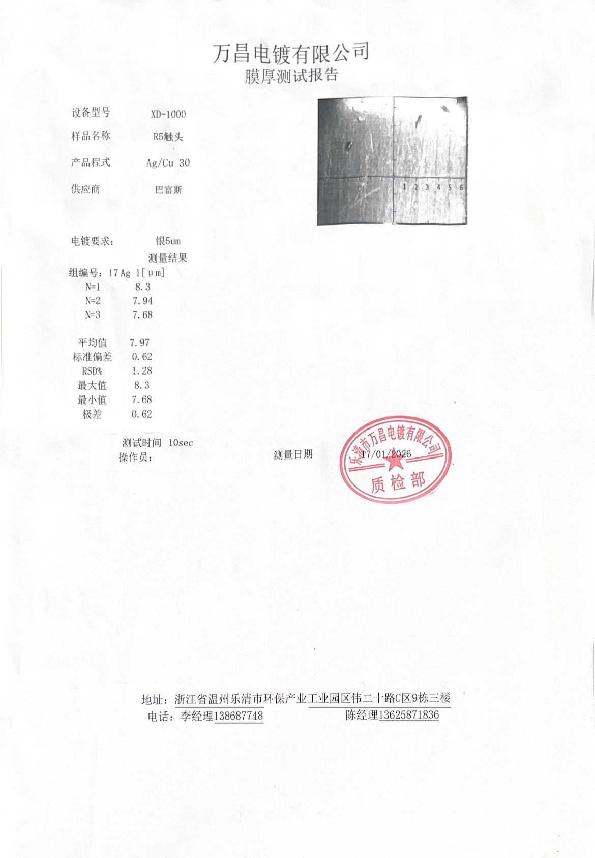
Figure 2 — Silver-plated copper surface. Plating specification is a purchasable line item, not a decorative detail.
Two implications follow for buyers. First, plating thickness belongs in the technical annex of the purchase order, because surface condition affects contact resistance over service life. Second, the derating decision sits partly with the panel builder: a busbar installed in a high-ambient enclosure without conductive grease will run warmer than the same busbar in a ventilated cabinet, and no supplier specification can compensate for that.
On the compliance side, IEC 61439-6:2025 covers low-voltage switchgear and controlgear assemblies — busbar trunking systems — and the standard version listed in the current reference set carries an effective date of 2025-12-01. It is a system-level standard, so a busbar component assessment supports compliance work; it does not replace the assembly-level verification the panel builder performs.
Where each model fits
The clearest way to separate the three models is by the panel they belong in.
BP3 in mains distribution and sub-main boards
Three-pole MCCB busbars suit boards where a single large incoming device feeds a set of three-phase outgoing ways at lower current. The 250 A to 800 A incoming band covers the feed side, while the 125 A to 400 A outgoing band covers the distribution side. Projects that specify a stepped distribution arrangement — one feed, several sub-feeds — are the natural fit.
BP5 in two-pole MCCB configurations
Two-pole MCCB assemblies appear where the protective device operates on two conductors. Typical placement is in boards dedicated to single-phase distribution fed from an MCCB frame, and in panel arrangements where a neutral conductor is switched or isolated alongside the phase.
BP6 in MCB final distribution boards
BP6 is the MCB-side model: a 250 A rated assembly with terminal widths sized to miniature circuit breaker terminals. It belongs in final distribution boards and distribution box applications, where the requirement is compact layout and simplified wiring rather than high current throughput. Barfuse's comparison material notes that the busbar format is more suitable than cable for distribution box applications because the compact design and simplified wiring reduce assembly complexity.
Busbar versus cable, and where the busbar case stops
The case for a pan assembly busbar over conventional cable connections rests on four documented claims: easier installation, higher conductivity, KEMA/DEKRA certification, and strict laboratory quality inspection. Barfuse's comparison data quantifies two of them — up to 90% reduction in installation time compared with cable, and a conductivity improvement of 20%. The same data describes cost as broadly similar between the two approaches, with less maintenance and high durability on the busbar side, and notes lower resistance loss during transmission that reduces energy consumption loss.
Those figures are real, but they are conditional, and buyers should understand the conditions before treating them as a forecast for their own panel.
- Busbar geometry is fixed at order. Cable can be re-routed around a late design change; a busbar cannot. If breaker selection is still open when the busbar is released, the 90% installation-time advantage can be consumed by a replacement order.
- The time saving scales with repetition. A pre-assembled busbar pays back on panels with many outgoing ways and repeatable layouts. For a one-off panel with few circuits, cable remains a practical and often simpler choice.
- Temperature rise is an installation concern as much as a product concern. Enclosure ventilation, torque discipline and contact treatment all affect the outcome, which is why the temperature-control measures above are stated as a combination rather than a single material property.
On material, this comparison concerns copper-based pan assemblies. Aluminum busbars are a separate segment; Precedence Research forecasts a 6.9% CAGR for aluminum busbars over 2026 to 2035, driven by lower weight and cost optimization in large infrastructure. Buyers evaluating aluminum should treat it as a distinct material decision with its own conductivity and termination requirements, not as a drop-in substitute within this three-model comparison.
Purchasing terms and acceptance criteria
The most useful output of a comparison is a purchase order that cannot be interpreted two ways. The checklist below converts the parameters above into order lines and inspection points.
| Order line | What to state | What it prevents |
|---|---|---|
| Model and breaker family | BP3 (MCCB 3P), BP5 (MCCB 2P) or BP6 (MCB) | Receiving a busbar built for the wrong device family |
| Incoming rating | BP3: 250 A, 400 A, 630 A or 800 A; BP5 and BP6: as configured | Mismatch between the feed device and the busbar |
| Outgoing rating | BP3: 125 A, 250 A or 400 A; BP5: 63 A to 400 A; BP6: 250 A rated | Outgoing ways rated below the connected load |
| Terminal width | BP6 outgoing 6.5 × 12 mm; incoming 21 × 22 mm; other models per configuration | Breaker terminals that do not seat |
| Pole distance | Exact value within the 25 mm to 45 mm range, stated numerically | Device misalignment and re-drilling |
| Conductor and plating | Copper conductive parts; silver-plated surface per specification | Contact resistance disputes at inspection |
| Insulation | Polycarbonate | Substitution with unspecified material |
| Certification evidence | KEMA/DEKRA, VDE, CB and SAA documentation on file | An incomplete project acceptance file |
| Customization scope | OEM parameters confirmed in writing: rating, pole distance, terminal geometry | Assumed customization that was never agreed |
Table 2 — Purchase-order fields and the failure each one prevents.
Two practical notes on acceptance. First, insulation and plating should be verified by document and by sample rather than by visual impression, since neither is reliably judged from a photograph. Second, where a project is subject to third-party inspection, the certificate set should be assembled before shipment, not after arrival — the 250 A certification document shown below is typical of the evidence a buyer should expect to receive as part of the file.
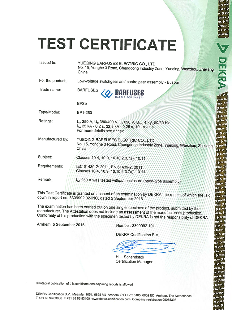
Figure 3 — Third-party certification evidence for a 250 A rating; part of the acceptance file, not the sales brochure.
Market context: why pan assembly comparison is becoming a procurement discipline
Busbar demand is growing, and the growth is concentrated in the formats that make comparison necessary. Precedence Research values the global busbar market at USD 19.83 billion in 2025, and market-size estimates vary by source — Stratview Research reports USD 15.72 billion while IMARC reports USD 20.3 billion, a spread generally attributed to whether locally fabricated busbars are counted alongside factory-assembled systems. The absolute figure should therefore be read as a range indicator rather than a precise number.
Two structural signals are more useful to a panel builder than the headline size. Laminated busbars are forecast at an 8.9% CAGR in high-density applications, according to Congruence Market Insights, which points to continued pressure for compact, pre-engineered conductor assemblies. And China accounts for over 30% of global copper processing capacity, according to the same source, which explains why the supply base for copper pan assemblies is deep and price-competitive, and why differentiation increasingly rests on documentation and geometry control rather than on material availability.
The standards side is moving in the same direction. IEC 61439-6:2025 addresses busbar trunking systems at the assembly level, and its effective date of 2025-12-01 reinforces a procurement habit that already exists in well-run projects: the busbar is assessed as part of a verified assembly, not as an isolated component bought on amperes alone.
Future outlook
Three developments are likely to shape how buyers compare pan assembly busbars over the next several years. The first is documentation depth: as assembly-level standards become more explicit, the supplier who can produce certification, plating specification and dimensional records quickly will be easier to qualify. The second is material competition — aluminum growth in large infrastructure will not displace copper in compact pan assemblies in the near term, but it will make material specification an explicit order line rather than an assumption. The third is customization discipline: because pole distance and terminal geometry are fixed at manufacture, the buyers who benefit most from pre-assembled busbars will be those who lock device selection before releasing the busbar order.
For BP3, BP5 and BP6 specifically, the comparison is unlikely to resolve into a winner. It will resolve into clearer specification practice: three-pole MCCB distribution for stepped three-phase boards, two-pole MCCB distribution for two-conductor arrangements, and the 250 A rated MCB assembly for final distribution where terminal dimensions of 6.5 × 12 mm and 21 × 22 mm define the interface.
FAQ
What is the difference between BP3, BP5 and BP6 pan assembly busbars?
They serve different breaker families. BP3 is a three-pole MCCB pan assembly with outgoing ratings of 125 A, 250 A and 400 A and incoming ratings of 250 A, 400 A, 630 A and 800 A. BP5 is a two-pole MCCB pan assembly covering 63 A, 125 A, 250 A and 400 A. BP6 is an MCB pan assembly rated at 250 A, with outgoing terminals of 6.5 × 12 mm and incoming terminals of 21 × 22 mm. All three use copper conductive parts and polycarbonate insulation.
How do I choose between a three-pole and a two-pole MCCB pan assembly busbar?
Start from the protective device, not from the current rating. A three-pole MCCB assembly such as BP3 is used where the device interrupts three conductors, which is typical of three-phase distribution with one incoming feed and several outgoing ways. A two-pole MCCB assembly such as BP5 is used where the device operates on two conductors. Because pole count determines the busbar layout, the decision cannot be reversed later by changing the current rating; a 400 A two-pole requirement is a BP5 configuration, not a BP3 one.
What current ratings are available across BP3, BP5 and BP6?
BP3 provides outgoing ratings of 125 A, 250 A and 400 A, and incoming ratings of 250 A, 400 A, 630 A and 800 A. BP5 covers 63 A, 125 A, 250 A and 400 A. BP6 is rated at 250 A. The incoming and outgoing bands are not identical on every model, so the order should state both figures separately rather than a single amperage.
Which dimensions should be written into a purchase order for a pan assembly busbar?
At minimum: terminal width, pole distance, and the current rating at both incoming and outgoing sides. For BP6, the published terminal widths are 6.5 × 12 mm outgoing and 21 × 22 mm incoming. Pole distance across the pan assembly family spans approximately 25 mm to 45 mm, so the exact value must be stated numerically for the breaker series in use. Conductor material, plating specification, insulation material and the certification file should also appear as separate order lines, because none of them can be verified from a current rating alone.
Are BP3, BP5 and BP6 available with OEM customization?
Yes. Customization and OEM supply are available across the three models. Because pan assemblies are manufactured to a fixed geometry, the customization scope — which parameters change and to what values — should be confirmed in writing before production. Rating, pole distance and terminal geometry are the parameters most often customized, and each of them affects the tooling or assembly setup rather than only the documentation.
Reference
The full Barfuse product catalogue, including busbar and distribution box ranges, is available for download: Barfuse Catalogue (PDF).
Tem questões ou precisa de mais detalhes?
Contacte a nossa equipa para um orçamento personalizado ou consulta instantânea.
Solicitar orçamento
Preencha o formulário abaixo e a nossa equipa entrará em contacto com uma proposta personalizada.
Chat direto do WhatsApp
Prefere conversar em tempo real? Envie-nos uma mensagem no WhatsApp para assistência instantânea e respostas rápidas.
- Obter orçamento personalizado
- Partilhar fotos ou documentos
- Discuta as suas necessidades diretamente
Geralmente responde em 5–30 minutos durante o horário de expediente.