
BP3 vs BP5 vs BP6 Pan Assembly Busbars: Buyer Comparison
A pan assembly busbar stops a distribution board from being a field-wired assembly and turns it into a repeatable modular product. That shift moves a large share of the engineering risk into component selection: once pole configuration, current class and terminal geometry are fixed, the board design is largely fixed with them. The BP3, BP5 and BP6 pan assembly busbars occupy three different positions in that decision space, which is why comparing them side by side is more useful to a buyer than ranking them.
Yueqing Barfuse Electric Co., Ltd. (BARFUSE) is a low-voltage electrical manufacturer based in Wenzhou, Zhejiang Province, China, founded in 2014. The company produces low-voltage fuse switch disconnectors, busbar systems and high and low voltage distribution wiring management products, including MCB pan assembly and MCCB pan assembly, and states that approximately 90% of its output is exported to markets including the Middle East, Russia, Latin America, Central Asia, the EU, Africa and Oceania.
This comparison is written from a buyer's perspective and is limited to published specification data for the three models. It deliberately does not declare a single best model, because the three assemblies answer different panel-design questions rather than competing for the same slot.
What a Pan Assembly Busbar Does Inside a Distribution Board
A pan assembly busbar is a pre-formed conductive assembly that distributes power from the incoming device to a row of outgoing protective devices inside a low-voltage distribution board. In modular boards it replaces individual cable links between the incoming breaker and each outgoing way, so the conductor path becomes a fixed, factory-made part instead of a field-fabricated one.
The three models discussed here share the same basic material build: copper conductors combined with PC (polycarbonate) insulating and mounting parts. They also share the same stated application environment — industrial application and commercial building electric management. What separates them is the outgoing device they are built around, the current class they are rated for, and the geometry of their terminals.
BP3, BP5 and BP6 at a Glance
The published data for the three models is summarised below. The table is the fastest way to see that these are not interchangeable alternatives but three product families with different outgoing devices.
| Model | Product type | Pole configuration | Current rating | Outgoing configurations | Material |
|---|---|---|---|---|---|
| BP3 | MCCB 3P Pan Assembly | MCCB, three-pole | Incoming: 250 A, 400 A, 630 A, 800 A Outgoing: 125 A, 250 A, 400 A | 2W, 4W, 6W, 8W, 10W, 12W, 14W | Copper + PC parts |
| BP5 | MCCB 2P Pan Assembly busbar | DP MCCB, two-pole (pole distance 25 mm, width 50 mm) | Incoming: 125 A (T 4 mm), 250 A (T 6 mm), 400 A (T 10 mm) Outgoing: 63 A (T 2 mm), 125 A (T 3 mm) | 2W to 40W | Copper + PC parts |
| BP6 | MCB 3P chassis busbar | MCB | Rated: 250 A | Mounting plate customizable according to the outgoing MCB | Copper + PC parts |
Table 1. Published specification summary for the BP3, BP5 and BP6 pan assembly busbars (Barfuse product data).
Pole Configuration: 3P MCCB, DP MCCB and MCB Chassis
The single most important difference between the three models is the outgoing protective device they are designed around. Buyers generally make that decision first, because it follows from the electrical design of the board rather than from the busbar catalogue.
- BP3 — MCCB 3P. Built for three-pole moulded case circuit breakers. It is the choice when outgoing ways are three-phase MCCB feeders, and the published data states that the series can be used with MCCBs from different brands whose pole distance is 25 mm, 30 mm, 35 mm or 45 mm.
- BP5 — DP MCCB. A two-pole pan assembly intended for branch DP MCCB devices with a pole distance of 25 mm and a width of 50 mm. It suits panels where outgoing protection is single-phase or two-pole rather than three-pole.
- BP6 — MCB chassis. A chassis busbar for MCB-based boards, rated 250 A, with a mounting plate that can be customized according to the outgoing MCB. It addresses the modular MCB end of the market rather than the moulded case end.
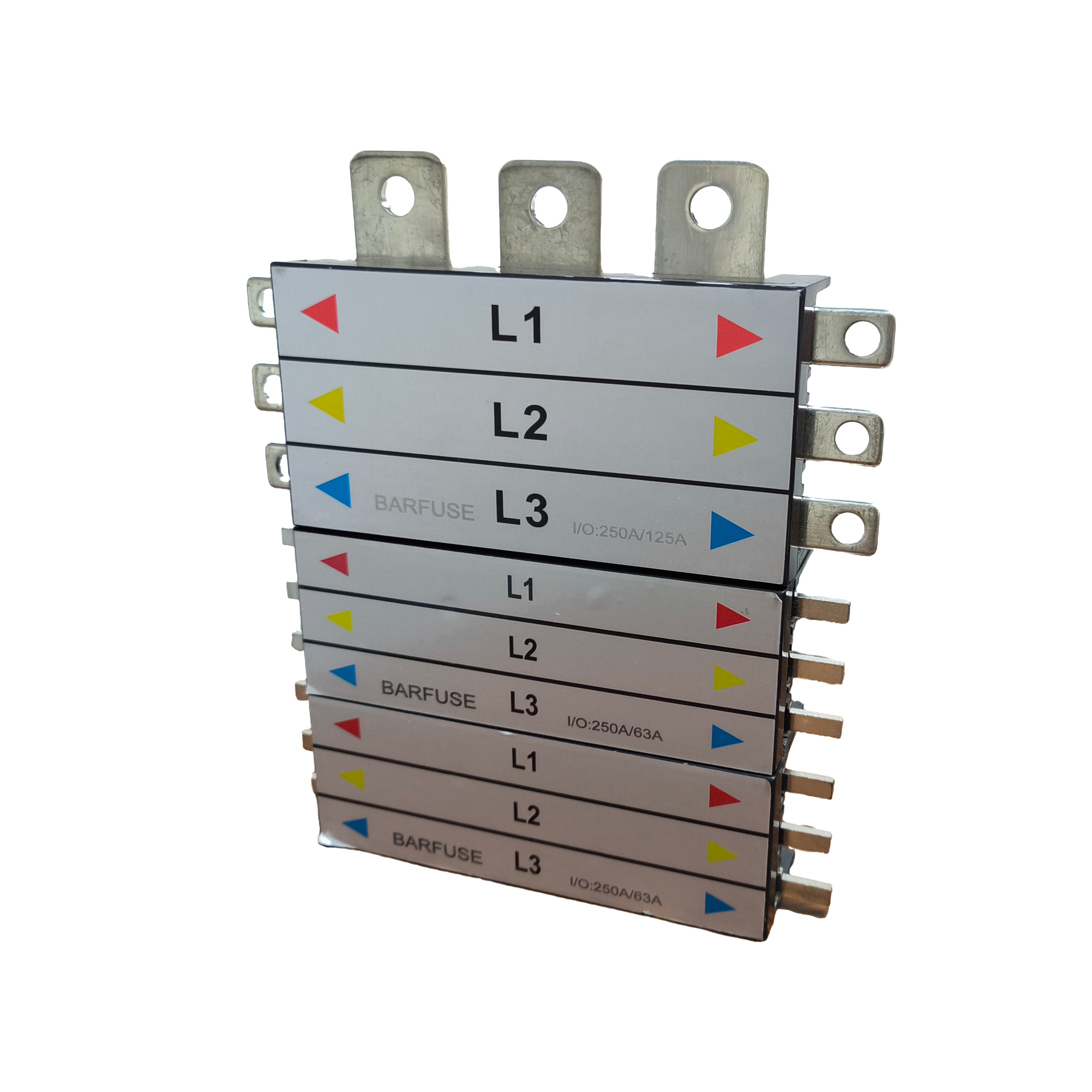
Branch MCCB and MCB devices determine which pan assembly busbar family a board design can use.
A practical consequence follows from this: a single project can legitimately use more than one of these families in different sections. The selection question is usually not "which one" but "which one for this section of the board".
Current Ratings and Conductor Thickness
Current rating is the second decision axis, and it is where the three models diverge most in how much information the published data provides.
BP3 publishes incoming ratings of 250 A, 400 A, 630 A and 800 A, with outgoing ratings of 125 A, 250 A and 400 A, across 2W to 14W outgoing configurations. That range places it in the higher current part of the modular busbar spectrum, where the incoming device is a large moulded case breaker rather than a miniature breaker.
BP5 ties current directly to conductor thickness: incoming 125 A at T 4 mm, 250 A at T 6 mm and 400 A at T 10 mm, with outgoing ratings of 63 A at T 2 mm and 125 A at T 3 mm. For a buyer this is the more useful form of specification, because it makes the sizing relationship explicit — the ampere figure is a function of the bar thickness, not an independent claim. It also supports the widest outgoing count in this comparison, from 2W to 40W.
BP6 is published as a single 250 A rating for the chassis busbar. That is a clear ceiling: it is an MCB-class assembly, not a substitute for an MCCB pan assembly in a high-current incomer position. Where a board needs an 800 A incomer, BP6 is not the relevant product, regardless of how the outgoing ways are arranged.
Terminal Geometry: The Specification Buyers Most Often Get Wrong
Terminal geometry is the least glamorous part of a busbar comparison and the most common cause of a board that cannot be assembled as drawn. Different breaker brands use different terminal layouts even at the same current rating, so the geometry of the busbar has to match the devices actually specified in the bill of materials.
| Model | Incoming terminal | Outgoing terminal | Stated compatibility |
|---|---|---|---|
| BP3 | Customized to the customer's MCCB (no fixed dimension published) | Not separately published | Usable with MCCBs of different brands at pole distance 25 mm / 30 mm / 35 mm / 45 mm; OEM acceptable, sizes customizable to the customer's MCCB |
| BP5 | Width 25 mm | Width 15 mm | Branch DP MCCB with pole distance 25 mm and width 50 mm |
| BP6 | 21 × 22 mm | 6.5 × 12 mm | Mounting plate customizable according to the outgoing MCB |
Table 2. Terminal geometry and stated device compatibility, as published by the manufacturer.
Two observations are worth making. First, BP6 is the only model in this set with fully published terminal dimensions in both directions, which makes it comparatively easy to check against an existing board design before ordering. Second, BP3 is published as a customizable platform rather than a fixed-geometry part: its incoming side is built to the customer's MCCB, and the compatibility statement covers four pole distances. That flexibility is an advantage, but it also means the buyer carries the responsibility of supplying accurate breaker data — pole distance, terminal arrangement and current rating — for the specific MCCB being used.
BP5 sits between the two: its terminal widths (25 mm incoming, 15 mm outgoing) are fixed and published, and the device envelope is narrow and specific — DP MCCB with 25 mm pole distance and 50 mm width. That narrowness is a strength in repetitive panel building and a constraint if the project mixes devices outside that envelope.
Material Build: Copper Conductors in PC Housings
All three models use copper conductors with PC parts. Copper remains the dominant conductor material in busbar systems generally: published market research puts copper busbars at 62.8% of busbar market share by material in 2025, with aluminium busbars forecast to grow at a 6.9% CAGR over 2026–2035, driven largely by weight and cost considerations in large infrastructure. Buyers evaluating these three models should therefore read the copper-and-PC build as a mainstream choice rather than a premium claim, and should expect aluminium alternatives to appear in larger or more cost-sensitive projects.
Where aluminium becomes relevant, the trade-off is usually conductor cross-section against weight and cost — a larger aluminium section is needed to carry the same current as a given copper section. That has knock-on effects on terminal geometry and enclosure space, which is precisely the part of the design that the terminal dimensions in Table 2 constrain.
Which Buyer Profile Each Model Suits
Because the models are not direct substitutes, the most useful comparison is a mapping between buyer profile and product fit.
| Buyer profile | Likely fit | Why, based on published data |
|---|---|---|
| Panel builder producing three-phase MCCB-fed boards with a high-current incomer | BP3 | Incoming ratings to 800 A, outgoing MCCB ratings of 125 A / 250 A / 400 A, up to 14 outgoing ways, and stated cross-brand MCCB compatibility at four pole distances |
| Builder of DP MCCB branch distribution panels with many single-phase outgoing ways | BP5 | DP MCCB envelope (25 mm pole distance, 50 mm width), outgoing configurations from 2W to 40W, outgoing ratings of 63 A and 125 A |
| Builder of MCB-based three-phase modular boards up to 250 A | BP6 | MCB chassis busbar rated 250 A with a mounting plate customizable to the outgoing MCB and fully published terminal dimensions |
| OEM buyer needing an assembly sized to a specific MCCB brand already designed in | BP3 | OEM is stated as acceptable and sizes can be customized to the customer's MCCB |
Table 3. Buyer profile mapping. Selection should follow the outgoing device type and current class required by the board design.
Modular Assemblies Versus Traditional Cable-and-Lug Wiring
Conventional distribution boards are frequently wired point-to-point with insulated cable that is cut, stripped, bent and terminated on site. The approach is flexible and familiar, but it moves conductor geometry, torque control and insulation integrity into the field, where they depend on the individual installer.
Modular pan assembly busbars change that distribution of risk. Conductor paths are formed in the factory, the number of discrete terminations falls, and the same geometry can be repeated across a production run. For panel builders working on repeat orders, the payback is largely in assembly time and consistency rather than in material cost.
The trade-off is design rigidity. A modular assembly is built for a specific outgoing device type, current class and pole geometry, so late changes to the breaker selection are more disruptive than they are with cable wiring. That is the price of repeatability, and it argues for finalising the bill of materials before the busbar specification is frozen.
Limitations and Verification Points Before Ordering
Three practical boundaries apply to this comparison, and buyers should treat them as part of the specification rather than as fine print.
- Certification scope is model-specific. The DEKRA test certificate held by Barfuse (numbers 3309992.100 and 3309992.101, issued by DEKRA Certification B.V. on 5 September 2016 and valid to 5 September 2099) covers busbar as low-voltage switchgear and controlgear assembly — specifically models BP1-125 and BP1-250, brand BARFUSES, series BFSe, open-type assembly without enclosure, to IEC 61439-2:2011 and EN 61439-2:2011. The BP3, BP5 and BP6 models are not listed in that published scope. Buyers who need a type-tested assembly for a named model should confirm the applicable certificate scope with the supplier instead of assuming blanket coverage across the busbar range.
- Quality system coverage is broader but still specific. The company's ISO 9001 certificate (62724Q1160R0S, issued by Jingxin Certification (Beijing) Co., Ltd., valid from 8 November 2024 to 7 November 2027, to GB/T 19001-2016 idt ISO 9001:2015) covers manufacturing and export of strip fuse disconnectors, load disconnectors, busbar systems including MCCB/MPCB busbars, and distribution boxes. This is a management-system certificate, not a product type test, and it should not be presented to a specifier as a substitute for one.
- Geometry must be verified against the real breaker. For BP3, terminal dimensions are not published as fixed values because the assembly is sized to the customer's MCCB; for BP6, the mounting plate is customized to the outgoing MCB. In both cases the risk of mismatch sits with the accuracy of the breaker data supplied by the buyer.

Verification of pole distance, terminal geometry and documentation is normally completed before a first order is released.
Customization, Lead Time and Order Execution
For buyers at the execution stage, the commercial parameters matter as much as the technical ones. The published figures for Barfuse are as follows: production modes include OEM and ODM; customization covers color, logo, material, new design, surface treatment, mold development and packing; monthly capacity is 8,000 pieces; lead time is 15 to 45 days; minimum order quantity is 1 piece; and quality control is described as 100% test.
On the procurement side, the stated delivery methods are FOB, CIF, CFR and EXW; acceptance is by pre-shipment test; and payment options include T/T, PayPal, Western Union and L/C. After-sales support is provided as remote technical support. For a first order of a customized assembly, the 15–45 day window is the parameter to plan around, since it spans both the standard and the customized case.
Market Context: Why Modular Busbars Are Getting More Attention
Busbar demand is rising in absolute terms. Precedence Research valued the global busbar market at USD 19.83 billion in 2025, with copper busbars accounting for 62.8% of share by material in the same year and aluminium busbars forecast to grow at a 6.9% CAGR over 2026–2035. In high-density applications, laminated busbars have been forecast to grow at an 8.9% CAGR.
Supply-side factors reinforce the trend. China accounts for over 30% of global copper processing capacity, which keeps a large share of busbar fabrication close to the copper supply chain. On the standards side, IEC 61439-6:2025, covering busbar trunking systems, has an effective date of 1 December 2025, continuing the update cycle for low-voltage switchgear and controlgear assemblies. For buyers, the practical implication is that documentation expectations are rising in step with the installed base: assemblies are increasingly judged on traceable ratings and declared geometries, not only on price per way.
Future Outlook
Three directions are visible from the data. First, modularisation continues, because panel builders under labour pressure favour factory-formed conductor paths over field fabrication. Second, material mix will shift gradually rather than abruptly: copper remains dominant by share, while aluminium growth is being driven by weight and cost in large infrastructure. Third, selection is becoming a documentation exercise as much as an engineering one — the models that are easiest to specify are the ones with published geometry and clearly scoped certificates.
For the BP3, BP5 and BP6 families specifically, the near-term evolution is likely to be in customization depth rather than in radical redesign, since the underlying breaker standards and terminal conventions they serve are stable. Buyers planning multi-year panel programmes should therefore treat the pole distance and terminal geometry of the assemblies as a design lock-in point and confirm it early, while treating current ratings and outgoing counts as configurable within the published ranges.
FAQ
What is the difference between the BP3, BP5 and BP6 pan assembly busbars?
BP3 is an MCCB 3P pan assembly with incoming ratings of 250 A, 400 A, 630 A and 800 A, outgoing ratings of 125 A, 250 A and 400 A, and 2W to 14W configurations. BP5 is an MCCB 2P (DP) pan assembly with incoming ratings of 125 A, 250 A and 400 A, outgoing ratings of 63 A and 125 A, and configurations from 2W to 40W. BP6 is an MCB 3P chassis busbar rated 250 A with a mounting plate that can be customized according to the outgoing MCB. All three use copper conductors with PC parts and are intended for industrial and commercial building electrical management.
How do current ratings relate to conductor thickness in these assemblies?
For BP5 the published data ties current directly to conductor thickness: incoming 125 A at T 4 mm, 250 A at T 6 mm and 400 A at T 10 mm, with outgoing ratings of 63 A at T 2 mm and 125 A at T 3 mm. BP3 publishes current steps without thickness values — incoming 250 A to 800 A, outgoing 125 A to 400 A. BP6 is published as a single 250 A rating. Buyers should treat the thickness figure as the sizing reference where it is given, rather than reading the ampere figure alone.
Do BP3, BP5 and BP6 share the same certification coverage?
No single published certificate covers all three. Barfuse holds a DEKRA test certificate (numbers 3309992.100 and 3309992.101, DEKRA Certification B.V., issued 5 September 2016, valid to 5 September 2099) whose published scope is busbar as low-voltage switchgear and controlgear assembly — models BP1-125 and BP1-250, brand BARFUSES, series BFSe, open-type assembly without enclosure, to IEC 61439-2:2011 and EN 61439-2:2011. BP3, BP5 and BP6 are not listed in that scope. The company also holds ISO 9001 certification (62724Q1160R0S, Jingxin Certification (Beijing) Co., Ltd., valid 8 November 2024 to 7 November 2027) covering manufacturing and export of busbar systems including MCCB/MPCB busbars. Specifiers requiring a type-tested assembly for a specific model should confirm the applicable scope directly.
Can these pan assembly busbars be customized for a specific MCCB brand?
For BP3, the published data states that OEM is acceptable and that sizes can be customized according to the customer's MCCB, with the series usable across MCCB pole distances of 25 mm, 30 mm, 35 mm and 45 mm. For BP6, the mounting plate can be customized according to the outgoing MCB. BP5 is specified for branch DP MCCB with a pole distance of 25 mm and a width of 50 mm. General customization capability covers color, logo, material, new design, surface treatment, mold development and packing, with OEM and ODM as production modes.
What should a buyer verify before placing a first order?
Commercially, the published terms are a minimum order quantity of 1 piece, lead time of 15 to 45 days, quality control described as 100% test, delivery methods of FOB, CIF, CFR and EXW, acceptance by pre-shipment test, and payment by T/T, PayPal, Western Union or L/C, with remote technical support after sale. Technically, the critical checks are that the pole distance and terminal geometry of the chosen model match the breakers actually specified in the board, that the outgoing configuration (2W to 14W for BP3, 2W to 40W for BP5) matches the number of ways required, and that the certification documents needed by the project are available for that specific model.
Reference: a downloadable catalogue covering the Barfuse busbar and pan assembly range is available here — Barfuse Catalogue (PDF).