
BTR1 vs BTR2 Fuse Switch Disconnectors: Buyer Comparison
BTR1 vs BTR2 Fuse Switch Disconnectors: Buyer Comparison
BTR1 and BTR2 are both Stripe Fuse Switch Disconnectors made by BARFUSE Electric Co., Ltd., a Wenzhou-based manufacturer of low-voltage fuse switch disconnectors, busbar systems and distribution wiring management products. They are not two versions of one design: BTR1 is documented around a copper/DMC construction and a 12 kV rated impulse withstand voltage, while BTR2 is documented around a compact modular body with visualized safety, intelligent monitoring, IP30, a 10 kV Uimp rating, 1000 V Ui, 415/500/690 V Ue and 250/400/630 A Ith. For a buyer at decision stage, the useful question is which documented characteristic set fits the panel’s insulation coordination, current duty, isolation practice and operating environment — not which model wins in general.
This comparison is built only from characteristics supplied by the manufacturer. No side-by-side type test between BTR1 and BTR2 was available for review, so the sections below compare documented characteristics, explain what each figure does and does not establish for a panel builder, and set out the points to confirm in writing before a purchase order.
The company reports a 10,000 m² facility, 45 employees, a seven-engineer R&D team and annual output of 250,000 pieces across low-voltage fuse switch disconnectors, busbar systems and pan assemblies, with about 90% of sales exported to markets including the Middle East, Russia, Latin America, Central Asia, the EU, Africa and Oceania.
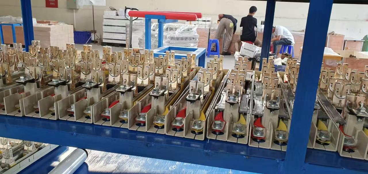
Insulated conductor detail from the manufacturing process; insulation and sleeving choices affect thermal behaviour in service.
Why the BTR1-versus-BTR2 decision starts at the panel, not the catalogue
Fuse switch disconnectors sit where three requirements meet: continuous current carrying, safe isolation, and short-circuit protection coordinated with the fuse link. A model that looks stronger on one datasheet line can be the weaker fit if the panel’s busbar spacing, enclosure protection or maintenance procedure was designed around a different arrangement.
Vertical fuse switch disconnectors are built for vertical busbar systems, and industry technical references describe them as optimised for 185 mm and 100 mm busbar spacing in LV networks. That single constraint already filters the shortlist: a device that does not match the panel’s busbar pitch forces a busbar redesign or an adaptor, and neither is free.
Three further questions do most of the sorting:
- What impulse withstand and insulation voltage does the panel specification actually require at 415–690 V?
- What current must be carried continuously, and what short-circuit figure must the switch-and-fuse combination be shown to withstand?
- How is isolation carried out in practice — all poles at once, or one phase at a time?
BTR1 and BTR2 answer these differently, and that difference is the substance of the comparison.
BTR1 Stripe Fuse Switch Disconnector: what the documented characteristics describe
BTR1’s documented profile points to a construction-led design. Its conductive path is described as copper, with DMC used in the construction. DMC (dough moulding compound) is a glass-reinforced thermoset moulding material widely used in low-voltage apparatus because it is dimensionally stable and does not soften at operating temperature the way thermoplastic housings can; in a fuse switch it belongs to the insulation and structural side of the design, not the current path.
Three figures define the electrical envelope as supplied:
- Rated impulse withstand voltage: 12 kV. This is the peak transient voltage the insulation is designed to withstand — an insulation-coordination parameter, not an operating voltage.
- Instantaneous breaking capacity: 1.3 IB, in the 50–100 kA band. The figure is stated as a range, and the reference current behind IB is part of what a buyer should pin down.
- Disconnection: three-phase simultaneous, or independent single-phase. Both an all-pole opening and a single-phase opening are documented, which changes how isolation and maintenance are planned.
What BTR1’s supplied profile does not state is equally relevant: no rated operational voltage, rated insulation voltage, thermal current or enclosure protection figure was included in the material reviewed here. That is an evidence gap to close with the manufacturer, not an indication that the model lacks those ratings.
BTR2 Stripe Fuse Switch Disconnector: what the documented characteristics describe
BTR2’s documented profile is built around compactness and operator visibility.
- Compact modular design — the housing and assembly are described as modular, which matters where a panel is laid out around repeated feeder modules and available depth is constrained.
- Visualized safety and intelligent monitoring — the model is documented as providing visible status information and monitoring functions. The supplied material does not specify the monitoring interface, signal type or communication protocol, so those details belong to the technical confirmation stage.
- IP30 — a device-level ingress protection rating.
- Rated impulse withstand voltage 10 kV; rated insulation voltage 1000 V; frequency 50/60 Hz.
- Rated thermal current 250 / 400 / 630 A; rated operational voltage 415 / 500 / 690 V.
- Limiting short-circuit capability 50–100 kA.
- Stated market focus: Nigeria and Congo.
The Ui of 1000 V against a maximum Ue of 690 V leaves headroom between the insulation rating and the operational voltage — the normal way a manufacturer signals that the device is intended for 690 V systems and not only for 415 V ones. The three current ratings also mean BTR2 is a family rather than a single article: 250 A, 400 A and 630 A frames should be quoted and checked separately.
BTR1 vs BTR2 at a glance
| Characteristic | BTR1 | BTR2 |
|---|---|---|
| Design centre | Construction and insulation margin | Compact modular build, visibility and monitoring |
| Construction | Copper with DMC | Compact modular design; material composition not specified in reviewed material |
| Rated impulse withstand voltage (Uimp) | 12 kV | 10 kV |
| Rated insulation voltage (Ui) | Not specified in reviewed material | 1000 V |
| Rated operational voltage (Ue) | Not specified in reviewed material | 415 / 500 / 690 V |
| Rated thermal current (Ith) | Not specified in reviewed material | 250 / 400 / 630 A |
| Frequency | Not specified in reviewed material | 50/60 Hz |
| Short-circuit figure as documented | 1.3 IB; 50–100 kA instantaneous breaking capacity | 50–100 kA limiting short-circuit capability |
| Disconnection | Three-phase simultaneous or independent single-phase | Not specified in reviewed material |
| Enclosure protection | Not specified in reviewed material | IP30 |
| Status and monitoring | Not specified in reviewed material | Visualized safety and intelligent monitoring; interface not specified |
| Stated market focus | Not specified in reviewed material | Nigeria, Congo |
Table notes: entries are limited to characteristics supplied by the manufacturer for this comparison. “Not specified in reviewed material” means the figure was absent from the supplied documentation; it does not mean the model lacks the capability.
Reading the insulation figures: 12 kV and 10 kV Uimp
The 2 kV difference between BTR1’s 12 kV and BTR2’s 10 kV rated impulse withstand voltage is a difference in insulation margin, not in working voltage. Impulse withstand levels are assigned during insulation coordination, where the required level follows the system voltage and the overvoltage category the installation is designed to. Both documented values sit above the levels normally associated with 415–690 V distribution circuits, so on a standard LV feeder the choice rarely turns on this line alone.
It becomes a real differentiator in three situations. First, where the panel specification or the end user’s standard sets a minimum Uimp that BTR2’s 10 kV does not meet — then the question is closed by the specification, not by preference. Second, where the panel belongs to a system with higher exposure to switching or atmospheric transients and the designer wants additional coordination margin. Third, where a common device type is standardised across panels at different system voltages and the higher figure simplifies the approved list.
The reverse also applies: specifying 12 kV where the panel only needs the lower coordination level adds cost and size without a corresponding change in protection behaviour. Uimp is a coordination input, not a measure of how well the device clears a fault.
Current, short-circuit and thermal behaviour
Two figures that look similar on paper answer different questions. A rated thermal current describes continuous current carrying. A short-circuit figure describes what the switch-and-fuse combination can withstand or interrupt under defined test conditions. Neither substitutes for the other, and a 630 A thermal rating says nothing about the short-circuit performance of the assembly.
For BTR2, the 250 / 400 / 630 A thermal current range is straightforward to use in panel design: the frame is selected against the feeder’s continuous load, with derating for enclosure temperature where the panel builder’s calculation requires it. BTR1’s supplied material does not state a thermal current, so a BTR1-based design must obtain that figure before the feeder schedule is fixed.
The 50–100 kA figures on both models deserve careful reading. A range rather than a single number normally reflects the influence of the fuse link fitted and of the conditions behind the rating. The buyer’s task is to establish, in writing, which fuse link and which test basis each end of the range refers to, and whether the figure is a breaking capacity of the switch alone or a conditional short-circuit rating of the switch-and-link combination. BARFUSE states the product operates in 24/7 mode; where that is the intended duty, continuous thermal performance rather than peak switching performance becomes the deciding measurement.
Material choices connect directly to temperature rise. BARFUSE documents its control methods for temperature rise and short-circuit risk as: properly increasing the rated current capacity, using conductive grease, adopting high-conductivity materials such as T2 copper, applying a 2 μm silver coating on surfaces, and covering conductors with heat-shrink tube. For a buyer, that list works better as an inspection agenda than as a slogan — conductor grade, plating thickness and insulation sleeving are all checkable on a sample, and each affects how much heat the same current produces at the terminal.
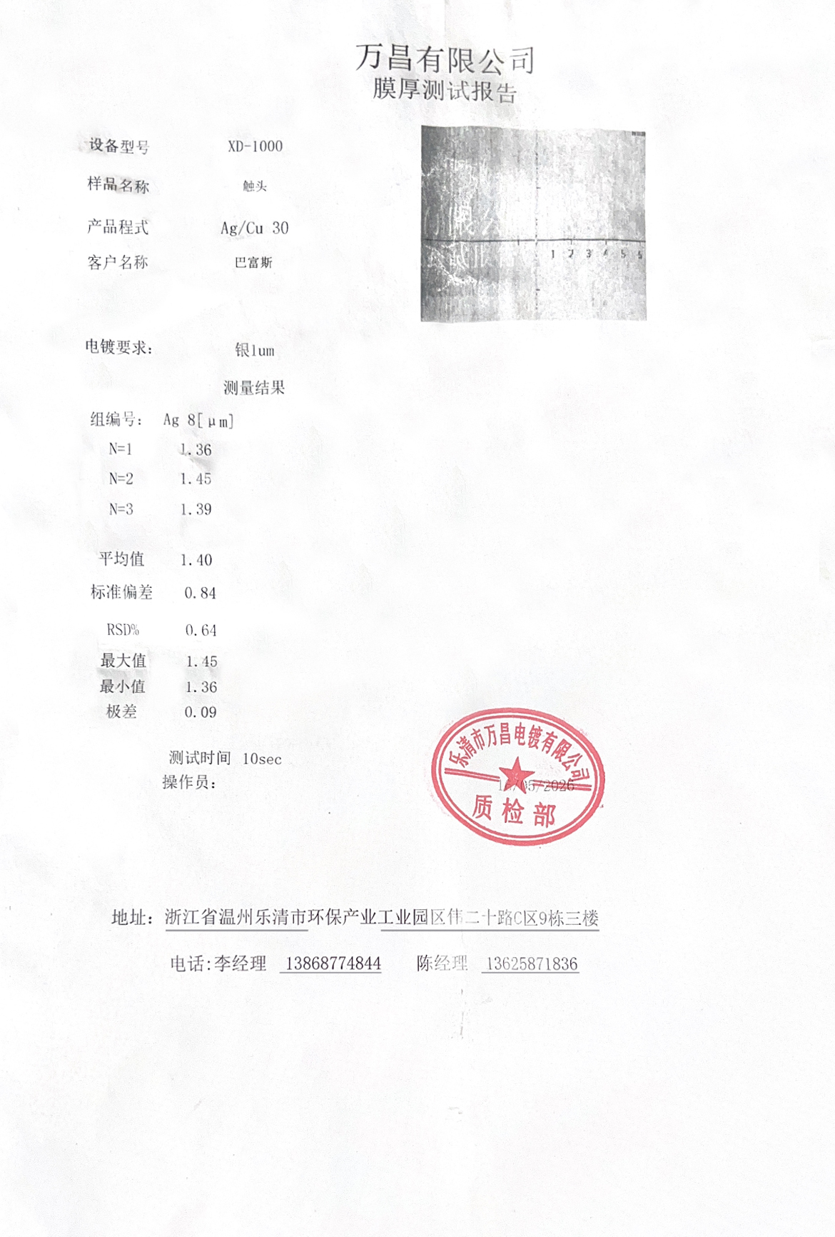
Silver-coated conductor sample documented by BARFUSE as part of its contact-surface process.
Disconnection mode and maintenance practice
BTR1’s documented support for three-phase simultaneous or independent single-phase disconnection is the characteristic most easily undervalued in a paper comparison. Three-phase simultaneous opening isolates a feeder in one operation, which suits routine isolation before work on a complete circuit. Independent single-phase opening allows one pole to be isolated while the others remain as they are, which fits phased maintenance, single-phase circuits fed from a three-phase board, and diagnostic work where the whole feeder does not need to come off.
The benefit is conditional on procedure. Single-phase operation improves safety only where the panel’s isolation procedure includes proving the correct pole dead, preventing back-feed from connected single-phase loads, and recording which pole was opened. Where the site’s switching programme is written around whole-feeder isolation only, the extra capability adds a training requirement rather than an operational gain.
BTR2’s supplied documentation does not state a disconnection mode, so a panel designed around independent single-phase isolation should not assume it without confirmation.
IP30 and what a device-level rating does not cover
BTR2’s IP30 rating means the enclosure protects against access to hazardous parts with a tool or object of 2.5 mm diameter or more, and against solid foreign objects of that size. The second digit is 0, which means no protection against water.
That has a direct consequence for panel design: IP30 is a property of the device, not of the finished installation. A feeder pillar, distribution cabinet or power pedestal reaches its stated protection level through its own enclosure, sealing and cable entry design. Where the installed environment involves rain, washdown or heavy dust, the panel enclosure must provide the protection, because the device rating will not.
Fit boundaries: which operating needs point to which model
Neither model is a default. The rules below follow the documented characteristics and should be checked against the project specification before a shortlist is fixed.
Operating needs that point toward BTR1
- The panel specification calls for a copper conductive path with DMC insulation and the construction method matters to the approving engineer.
- A minimum Uimp of 12 kV is written into the specification or the end user’s standard.
- Maintenance is organised around single-phase isolation on a three-phase board, and the switching procedure supports it.
- One device type must cover a range of system voltages with insulation margin to spare.
Operating needs that point toward BTR2
- The panel is laid out around repeated compact feeder modules and depth is constrained.
- Feeders fall in the 250–630 A range at 415, 500 or 690 V, and one family covering that spread simplifies the approved list.
- Visible status at the device and monitoring into the wider system are part of the operating requirement, with the interface confirmed at technical stage.
- The enclosure already provides environmental protection, so a device-level IP30 rating is consistent with the installation.
- The project is in the Nigerian or Congolese market, where BTR2 is the stated focus and local support and stock patterns are more likely to be built around it.
Where two of these pull in opposite directions — for example, a 690 V panel that also requires single-phase isolation — the specification should be resolved before the model is chosen, not after.
Verification points to fix before the purchase order
The list below converts the comparison into a written checklist. Each item is a question with a document as the answer, which is what makes it usable in a tender review.
- Complete the missing ratings. Obtain BTR1’s rated operational voltage, rated insulation voltage, thermal current and enclosure protection so both models can be compared like for like.
- Confirm the short-circuit basis. Ask which fuse link, which test standard and which conditions each 50–100 kA figure refers to, and whether it covers the switch alone or the switch-and-link combination.
- Check certificate scope per model. BARFUSE states it has obtained testing accreditations from KEMA (DEKRA) in the Netherlands and VDE in Germany, plus CB certification and SAA certification in Australia. Scope is model-specific in the company’s own documentation — its BTR4 material refers to a low-voltage switchgear and controlgear test report, and its VDE coverage is stated for BTR5. Ask which certificate covers the exact model and rating being supplied.
- Match the busbar spacing. Confirm the device against the panel’s vertical busbar pitch, since vertical fuse switch disconnectors are designed around 185 mm and 100 mm systems.
- Verify conductor and plating on a sample. Check conductor grade, silver coating thickness and heat-shrink coverage against the stated control measures, and confirm the sample matches the production configuration.
- Confirm the monitoring interface in writing. For BTR2, obtain the signal type, contact arrangement and any communication detail, since the supplied material describes monitoring without specifying the interface.
- Confirm the disconnection mode for the supplied frame. For BTR1, confirm that the ordered rating supports single-phase operation if the maintenance procedure relies on it.
- Confirm DC suitability separately if needed. The material reviewed does not state DC ratings for either model. IEC 60269-1:2024 covers low-voltage fuses for AC up to 1000 V and DC up to 1500 V, but a standard’s scope is not a product rating; DC and photovoltaic circuits need their own confirmation.
How the Stripe series compares with square fuse switches
Both models sit inside a family comparison that BARFUSE makes against square fuse switches. The company’s comparison material describes the core differences as high safety and reliable protection, high integration with flexible monitoring, modular design for space economy, and cost efficiency. The quantified version states a 50% improvement in safety performance, a 30% increase in space utilisation and a 20% lower cost relative to square fuse switches, with less maintenance, and positions the product for distribution cabinets, power pedestals and feeder pillars.
Those figures are manufacturer comparison statements. The supplied material does not state the test method, the baseline configuration or the measurement basis behind the percentages, so they should be treated as vendor claims to be tested against a project’s own acceptance criteria rather than as independent findings. They are also stated at product-family level rather than separately for BTR1 and BTR2, which means they cannot be used to separate the two models in this comparison.
What the family-level comparison does establish is the application envelope: distribution cabinets, power pedestals and feeder pillars are the intended settings, consistent with the vertical busbar arrangement both models are built for.
Market and standards context
The general standard behind these products moved recently. IEC 60269-1:2024, published in August 2024, sets updated general requirements for low-voltage fuses and covers AC applications up to 1000 V and DC applications up to 1500 V. For a buyer specifying 690 V equipment, the practical effect is that the standard’s voltage scope comfortably covers 415–690 V AC systems, and that any DC application must be assessed against the DC part of the scope with product-specific evidence.
Market sizing for the fuse category varies with scope. Fortune Business Insights projects the global electric fuse market at USD 5.84 billion in 2025, growing at a 7.05% CAGR towards 2034. That figure should be read alongside the known divergence in published estimates, which range from roughly USD 4.0 billion to USD 5.84 billion for 2025 depending on whether fuse bases and switch disconnectors are counted as separate mechanical switchgear — a reminder that category boundaries, not demand, often explain the gap between reports.
Trade data points to a similar conclusion on mix rather than volume. UN Comtrade reporting on HS code 853610, electrical fuses for under 1000 V, is tracked with volume shifts toward EV-related high-voltage components. That is a derived reading of trade flows, not a statement about LV panel demand in any single market, and it does not change the specification work on a 690 V feeder.
Outlook
Two developments are likely to shape how buyers read this comparison over the next specification cycles. The first is standards drift: with IEC 60269-1 refreshed in 2024, panel specifications that cite the standard by year will gradually be updated, and buyers should expect documentation requests to name the edition. The second is the shift toward DC and higher-voltage protection in adjacent applications, which puts pressure on manufacturers to state DC capability explicitly rather than leave it to inference.
For BTR1 and BTR2 specifically, the practical consequence is that the decision will keep resting on the same four documented variables — insulation coordination, current and short-circuit basis, disconnection mode and enclosure context — plus the completeness of the model-specific documentation. Buyers who close the evidence gaps in this article’s checklist will be comparing two fully specified devices; buyers who do not will be comparing two datasheets of unequal completeness.
FAQ
What is the main difference between BTR1 and BTR2 fuse switch disconnectors?
BTR1 is documented around a copper/DMC construction, a 12 kV rated impulse withstand voltage, a 1.3 IB instantaneous breaking capacity in the 50–100 kA band, and three-phase simultaneous or independent single-phase disconnection. BTR2 is documented around a compact modular design with visualized safety and intelligent monitoring, IP30, 10 kV Uimp, 1000 V Ui, 50/60 Hz, 250/400/630 A thermal current, 415/500/690 V operational voltage and a 50–100 kA limiting short-circuit capability. The difference is one of design centre rather than a ranked order.
Does a 12 kV rated impulse withstand voltage change the design of a 690 V LV panel?
Only where the specification requires it. Rated impulse withstand voltage is an insulation-coordination parameter, and both 10 kV and 12 kV sit above the levels normally associated with 415–690 V distribution circuits. A 12 kV requirement becomes decisive when the panel specification or the end user’s standard sets that minimum, when the designer wants extra coordination margin, or when one device type must serve panels at different system voltages.
How should a buyer verify the 50–100 kA short-circuit figures?
Ask for the fuse link, test standard and test conditions behind each end of the range, and confirm whether the figure applies to the switch alone or to the switch-and-fuse-link combination. A range normally reflects the influence of the link fitted and the test basis, so the figure should be tied to the exact configuration being purchased rather than quoted as a single capability number.
When is independent single-phase disconnection useful?
It is useful where maintenance is carried out phase by phase, where single-phase circuits are fed from a three-phase board, or where diagnostic work does not require isolating the whole feeder. It adds safety only where the isolation procedure includes proving the correct pole dead and preventing back-feed from connected loads; without that procedure it adds a training requirement rather than an operational gain.
Does IP30 on BTR2 make an installed panel IP30?
No. IP30 is a device-level rating: protection against access to hazardous parts and solid objects of 2.5 mm and above, with no water protection. The protection level of the finished installation comes from the feeder pillar, distribution cabinet or power pedestal enclosure, its sealing and its cable entries, so the enclosure design must carry the environmental requirement.
Further specification detail for the BTR series is available in the BARFUSE product catalogue (PDF).
Tem questões ou precisa de mais detalhes?
Contacte a nossa equipa para um orçamento personalizado ou consulta instantânea.
Solicitar orçamento
Preencha o formulário abaixo e a nossa equipa entrará em contacto com uma proposta personalizada.
Chat direto do WhatsApp
Prefere conversar em tempo real? Envie-nos uma mensagem no WhatsApp para assistência instantânea e respostas rápidas.
- Obter orçamento personalizado
- Partilhar fotos ou documentos
- Discuta as suas necessidades diretamente
Geralmente responde em 5–30 minutos durante o horário de expediente.