
Bench Review: 2+2 Power-Signal Combo vs Single-Purpose Connectors
A connector that carries both main power and a low-current signal line is a different product decision from a connector that carries power alone. For lithium-battery equipment, the choice between a 2+2 power-signal combo such as AOYG's DXT30U(2+2)-F(B) and a plain two-pole high-current connector is not a question of which part is stronger. It is a question of how much wiring an assembly can afford to carry, and what the battery management system actually needs to see.
AOYG DC Power Connector is a manufacturer of high-current DC connection systems for lithium-ion smart devices, operating a 6,000 m² production facility with a stated annual output of 900,000 units under an IATF16949:2016 quality management system. Its product line spans single-purpose high-current connectors and multi-contact combination connectors, which is what makes a like-for-like comparison possible rather than an abstract one.
Whether combining power and signal into one shell is the right answer depends on three testable things: whether the device has a battery management system that needs a signal path at all, how much current the power pair must carry, and how much harness complexity the assembly can absorb before it becomes the reliability problem.
Why connector count became a design constraint
Battery-powered equipment has moved steadily from a battery-and-switch arrangement to a battery, a battery management system, and some form of reporting or control. Temperature sensing, cell voltage monitoring, communication lines and enable signals each require a conductor. In a conventional layout, those conductors leave the pack through a second connector, a separate harness branch, and an additional sealing or strain-relief point.
That architecture works, but every added mating interface carries a cost: an extra assembly step, an extra contact pair that can corrode or loosen, an extra point where a technician can connect the wrong lead, and an extra surface to seal on equipment that sees moisture or vibration.
The counter-pressure is equally real. Fewer parts is only an improvement when the combined part is specified as carefully as the two parts it replaces. Consolidation moves risk rather than removing it, and the risk lands in the connector drawing.
What a 2+2 architecture actually is
A 2+2 connector places four contacts in a single housing: two power contacts sized for the main current path, and two signal contacts sized for sensing or low-current communication. In the DXT30U(2+2)-F(B) configuration referenced here, the power pair is rated to 20 A and the signal pair to 1 A or higher.
The distinction between the two pairs is the whole point. The signal contacts are not a second power path and are not rated as one. Equipment that draws load across all four contacts is misapplying the part, and that misapplication is the single most common way a combination connector underperforms a pair of dedicated ones.
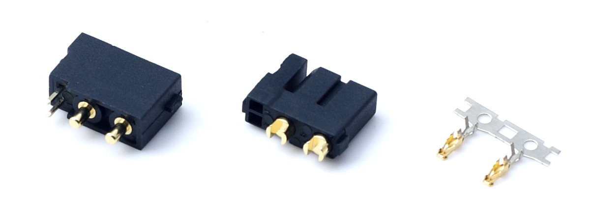
A 2+2 power-signal combo connector from AOYG's DXT30(2+2) series: two power contacts and two signal contacts in one shell, shown as a mated pair.
Where the engineering difficulty sits
Combining a 20 A path and a 1 A path in one body creates three design questions that a buyer should resolve from drawings rather than from a product photograph.
- Contact separation. The power pair generates heat under load; the signal pair does not. How much thermal and electrical isolation exists between the two pairs inside the housing determines whether signal integrity survives a warm power contact.
- Keying and orientation. A four-contact shell that can be mated in more than one orientation invites reversed power. Confirm the mechanical keying, and confirm it is different from the neighbouring product in the same family.
- Mating sequence. On some multi-contact designs the signal contacts are intended to engage before or after the power contacts; on others there is no deliberate sequence. Do not assume one behaviour or the other without written confirmation.
None of these questions has a universal answer. They are simply the questions that a 2+2 architecture makes unavoidable and a two-pole architecture makes irrelevant.
Where the combo architecture earns its place
The case for a combined connector is strongest where a device has a BMS that must communicate, but the power link itself is modest. Light e-bikes and compact smart devices sit in exactly that envelope: a controller, a display, a sensing line and a pack that all need to talk to each other, packaged into a housing where every additional connector is a visible cost.
AOYG's published comparison data positions its connector line for applications including drones, portable energy storage, e-scooters, power garden tools and intelligent robots, citing a compact structure with high load capacity alongside stable current transmission with low temperature rise and strong vibration resistance. Those are relevant properties for a combined part specifically because a combined part sits in the same vibration environment as the single-purpose connector it replaces, but carries more contacts that could be disturbed by it.
Signal monitoring without a second harness
The practical gain is not electrical; it is mechanical and procedural. One connector means one mating action during assembly, one connector to inspect at end-of-line, and one part number to stock for service. For a 20 A power link carrying a temperature-sense or communication line, that consolidation removes an entire branch of harness from the bill of materials.
Compactness under load
Where the enclosure is tight, a combined part occupies one cutout instead of two. That matters in service robots and compact smart devices where the connector often competes with the battery, the controller and the enclosure wall for the same few millimetres.
Where a single-purpose power connector remains the better answer
Neutrality requires stating the other side plainly, because in several common configurations the simpler part wins.
Pure power links with no signal requirement
If the device has no BMS reporting line and no telemetry, the extra signal pair does nothing except add two contacts to inspect, two contacts that can be contaminated, and a pinout that a field technician can get wrong. A two-pole connector in the same application is a simpler part with a simpler failure mode.
Current beyond the combo's envelope
The 2+2 body referenced here is specified at 20 A on the power pair. High-draw airframes and heavy UAV or RC builds routinely work in the 60 A to 90 A class, where a DXT30-form connector is not the appropriate part regardless of how well it performs at 20 A. Current class, not contact count, decides that question.
Standardised, field-replaceable ecosystems
XT60 and XT90 remain the primary industry standards for medium-to-high power non-proprietary RC aircraft and drone battery connections as of 2026, according to connector compatibility guidance published by ChinaHobbyLine. That installed base has practical consequences: spares are widely stocked, field replacement is a known procedure, and a repair technician already owns the mating half. A proprietary 2+2 combo has none of that ambient support unless the equipment maker chooses to provide it.
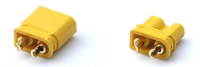
The simpler alternative: a two-pole high-current connector, where the only function is moving current and the only failure mode to inspect is the power contact pair.
Serviceability and pinout risk
A single-purpose connector can be replaced by anyone who can match two contacts. A combined connector must be replaced by someone who will match four, in the right orientation, with the signal pair intact. On equipment serviced in the field rather than at a depot, that difference is not cosmetic.
Head-to-head on the criteria that decide the choice
| Decision criterion | 2+2 power-signal combo (DXT30U(2+2)-F(B) class) | Single-purpose two-pole high-current connector |
|---|---|---|
| Current path | Power pair at 20 A; signal pair at 1 A or higher, not a load path | One contact pair sized for the full load current |
| Wiring count | One shell, one mating action for power and signal | Two connectors and a split harness when a signal line is needed |
| BMS monitoring | Supported inside the same connector body | Requires a separate connector or an external tap |
| Failure modes to inspect | Power contacts, signal contacts, keying, orientation | Power contacts and mating orientation only |
| Field service | Four contacts to match; pinout must be documented | Two contacts to match; replacement is widely understood |
| Best fit | Light e-bikes, smart devices, service robots, portable storage with a reporting line | Pure power links, high-draw airframes, standardised RC and UAV platforms |
| Ecological support | Depends on the equipment maker's parts strategy | XT60 and XT90 have a broad, established installed base |
Ratings as stated for the referenced product configuration. Buyers should confirm current, temperature-rise and environmental specifications against the supplier's drawing for the specific part number.
What the surrounding market data suggests
Three data points frame why this comparison is becoming more common in procurement reviews rather than less.
First, scale. Fact.MR valued the global high power connectors market at approximately USD 5.47 billion in 2025, which is a market large enough to support both specialised multi-contact designs and commodity two-pole parts side by side rather than one displacing the other.
Second, DC dominance in storage. Dataintelo reported that DC connectors represented 58.7% of the energy storage connector market in 2025, attributing the share to higher voltage requirements. As storage systems standardise on DC architectures, the connector becomes the natural place to also carry the monitoring line, which is the structural argument behind combination designs.
Third, load density. 5G base stations draw roughly 11.5 to 14 kW in typical operation, with peaks reaching 19 kW, according to telecom site planning guidance. Higher-density power infrastructure pushes connector selection toward fewer, better-specified interfaces rather than more of them.
None of these figures prove that a 2+2 combo is the right part for a given design. They do explain why the question is being asked more often, and why a buyer who cannot answer it from a drawing is exposed.
Reading AOYG's comparison claims without over-reading them
AOYG's published comparison material states a contact resistance reduction of over 50% relative to traditional high-current connectors, a 15–20% lower cost relative to alternatives, higher efficiency, less maintenance, and superior anti-spark performance with lower temperature rise. The same material cites strong vibration resistance and safe plug and unplug as reliability characteristics for dynamic applications such as drones and robots.
These are supplier comparison statements, and they should be treated as such. A contact resistance figure is only meaningful next to the test method, the reference part it was measured against, and the ambient conditions. The same applies to a cost percentage, which depends entirely on volume, termination method and the alternative being priced.
What the claims are useful for: framing the questions to put to a supplier. A stated reduction in contact resistance points to a temperature-rise question. A stated cost advantage points to a landed-cost question that includes termination, inspection and field failure. A stated anti-spark property points to a hot-plug scenario question.
What the claims are not: a substitute for the supplier's own test report on the specific part number being purchased.
A procurement checklist before the design freeze
- Confirm the signal requirement is real. If no BMS line, temperature sense or communication path exists in the device, the 2+2 architecture adds inspection burden without adding function.
- Verify the power rating against the actual duty cycle. A 20 A rating is a starting point; continuous versus peak, ambient temperature and connector housing all change the usable figure.
- Request the contact-resistance and temperature-rise test data for the exact part number, not the product family.
- Check the keying drawing. Confirm that the mating orientation is mechanically unique within the family so that a nearby connector cannot be forced into the wrong half.
- Confirm whether a defined mating sequence exists for the signal pair, and if so, that it matches the assembly method on the line.
- Ask about environmental rating explicitly. Combination housings are not automatically sealed, and equipment exposed to water, dust or washdown needs a stated ingress rating rather than an assumption.
- Assess the spare-parts path. A four-contact connector requires documented pinouts and stocked mating halves, particularly for equipment serviced away from a depot.
- Confirm the supplier's process controls. AOYG states IATF16949:2016 certification covering incoming inspection, tooling, automated production and finished-product testing, with 25 engineers supporting OEM and ODM customisation — relevant when a four-contact assembly has to hold position tolerances across a production run.
Future outlook
The direction of travel in lithium-battery equipment favours more monitoring, not less. Packs are expected to report state of health, temperature history and fault conditions, and each of those expectations adds a conductor that has to leave the enclosure somewhere. Combined connectors are one answer to that pressure, and they will keep appearing in compact designs where a second cutout is not available.
The counter-trend is equally durable. Standardised two-pole formats retain a strong position because their installed base, spares availability and field familiarity are genuine engineering assets, and no combination design has replaced them in high-draw airframes or in the RC and UAV battery ecosystem. For some years yet, the realistic outcome is not one architecture displacing the other, but designers choosing between them on a per-link basis.
What may change is the burden of proof. As combination connectors move from niche to commonplace, buyers are likely to ask for contact-resistance, temperature-rise and mating-cycle data on the combined assembly as a matter of routine rather than as an exception. Suppliers who already document those figures will find the conversation easier.
Frequently asked questions
What is the difference between a 2+2 power-signal connector and a single-purpose high-current connector?
A 2+2 connector houses two power contacts and two signal contacts in one shell, with the power pair rated for the main current path and the signal pair intended for sensing or low-current communication. A single-purpose two-pole high-current connector houses only the power contact pair. The difference is contact count and function, not current class: each has to be sized separately for the load it carries.
Can a 2+2 connector replace a dedicated power connector in a light e-bike or compact smart device?
It can, when the power demand sits within the connector's power-pair rating and the device genuinely uses the signal pair for BMS monitoring or communication. In the DXT30U(2+2)-F(B) configuration referenced here, the power pair is rated to 20 A and the signal pair to 1 A or higher, which places light e-bikes and compact smart devices inside the intended envelope. If the device has no signal line, the second pair adds inspection burden without adding function.
How should a buyer verify the current rating of a combined connector?
Verify it per contact pair, not per connector. Ask for the power-pair rating, the signal-pair rating, the test conditions behind both, and the temperature-rise data at the intended continuous load. Confirm also that the assembly does not route load current through the signal contacts, since that would invalidate the stated rating of the part.
Does the added signal pair increase failure risk?
It adds two contacts and a pinout that must be matched correctly during assembly and service. Whether that becomes a field failure depends on the housing keying, the availability of documented pinouts, and the discipline of the assembly process. A single-purpose two-pole connector carries fewer contact-level risks but loses the ability to monitor the pack inside the same interface.
Which applications should stay with single-purpose power connectors?
Links that need no signal path at all, links that exceed the combination part's power rating such as 60 A to 90 A airframe connections, and platforms built around standardised formats where spares and field familiarity matter. XT60 and XT90 remain the primary industry standards for medium-to-high power non-proprietary RC aircraft and drone battery connections as of 2026, which gives those formats a practical advantage in repairable equipment.
Are AOYG's stated comparison figures independently verified?
The figures — including a contact resistance reduction of over 50% and a 15–20% lower cost relative to alternatives — are published by AOYG as supplier comparison data and are not presented here as independently verified results. Buyers should request test conditions and the reference parts used before relying on them in a design decision.
Tem questões ou precisa de mais detalhes?
Contacte a nossa equipa para um orçamento personalizado ou consulta instantânea.
Solicitar orçamento
Preencha o formulário abaixo e a nossa equipa entrará em contacto com uma proposta personalizada.
Chat direto do WhatsApp
Prefere conversar em tempo real? Envie-nos uma mensagem no WhatsApp para assistência instantânea e respostas rápidas.
- Obter orçamento personalizado
- Partilhar fotos ou documentos
- Discuta as suas necessidades diretamente
Geralmente responde em 5–30 minutos durante o horário de expediente.