
CT Output Signals Decoded: mA Loops, RS485, Integrators and Raw AC for PLC Inputs
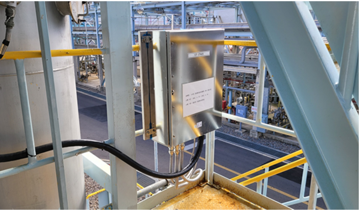
The output interface sits between the measured feeder and whatever consumes the signal: a PLC card, a Modbus host, or a meter with a current input.
A current transformer does not deliver a measurement. It delivers a signal, and the form of that signal decides what the rest of the installation has to look like. The same feeder can be clamped by a split-core CT with a raw AC secondary, by a loop-powered transmitter with a 4–20 mA DC output, or by a smart CT with an RS485 port — and each choice forces a different cable, a different input card, a different commissioning routine and a different share of signal processing between the sensor and the panel.
WENZHOU HEYI ELECTRICAL CO.,LTD (HEYI ELECTRICAL) is a current transformer and current sensor manufacturer established in 2012 in Wenzhou, Zhejiang, China, operating a 10,000 m² facility with a documented annual output of 356,000 units and a 95% export ratio across Southeast Asia, South Korea, Europe, South America, Australia, Africa, the Middle East and North America. Three of its split-core families are documented with the same 0–1000 A measurement range and the same 0–50 mm inner diameter class, but they terminate in three different signal interfaces: KCT, KCT-L and KCD. That overlap makes them a practical reference set for an output-format decision.
This reference is written for the evaluation stage, where the feeder range, the window size and the accuracy class have usually been settled, and the remaining question is what the control system will actually receive at its terminals.
Why the Output Interface Outweighs the Ratio Decision
Most current transformer specification sheets lead with ratio, accuracy class, burden and window size. Those parameters determine whether the CT can measure a given feeder accurately. They do not determine whether the measurement can reach the device that needs it.
Output format is often decided last, by whoever wires the panel, and that sequence is where rework appears. A CT ordered with a 5 A secondary cannot be connected directly to a standard PLC analog card: the card expects a DC voltage or mA signal, so the installation needs a current-input module or an external transducer. A 4–20 mA transmitter cannot be commissioned where no loop power exists at the measuring point. An RS485 device needs a communication port, a unique address, and a host that speaks the same protocol before a single value appears on screen.
The practical implication is that output format should be selected at the same time as the host device, not after it. The remaining sections separate the three architectures by what they deliver, how far that signal can travel, and how much work is left to the buyer.
The Three Output Architectures, Documented Side by Side
The table below reflects only the features documented for the three HEYI families in scope. It is intended as a comparison of interfaces, not a ranking of accuracy, because accuracy requirements come from the application rather than from the output type.
| Documented family | Signal at the terminals | Documented accuracy | Range / window | Documented roles |
|---|---|---|---|---|
| KCT — Split-Core Current Transformer | Raw secondary and low-level options: 5 A, 1 A, mA, mV | 3.0 / 1.0 / 0.5 | 0–1000 A; 0–50 mm | Split-core and clamp-on CT, miniature split-core CT, Class 0.5 split-core variant, ferrite-core and high-frequency noise-suppressing variants |
| KCT-L — True RMS Current Transformer / Transmitter | 4–20 mA DC output | 1.0 | 0–1000 A; 0–50 mm | Loop-powered current monitoring sensor, split-core current transmitter, IoT gateway compatible current sensor |
| KCD — Split-Core Current Transformer | RS485 / Modbus RTU digital output | 1.0 | 0–1000 A; 0–50 mm | Modbus RTU current and energy sensor, digital output current transducer, RS485 energy monitoring module, all-in-one AC power meter sensor |
Raw AC output: what “raw” actually means
KCT is documented with raw secondary and low-level output options — 5 A, 1 A, mA and mV — across accuracy grades of 3.0, 1.0 and 0.5, and the family includes a Class 0.5 split-core variant, a ferrite-core variant and a high-frequency noise-suppressing variant. In this architecture little conversion happens inside the housing: the CT produces a proportional AC signal and the receiving device is responsible for burden, scaling and true-RMS conversion.
That division of labour has two consequences. First, the measuring electronics stay in the panel, so this is the architecture that works where no auxiliary power is available at the measuring point. Second, the clamp-on split-core structure allows installation without breaking the primary conductor, which is why this construction is widely used when existing switchgear is being retrofitted rather than newly built.
The trade-off is equally clear. A raw secondary current cannot be read by a standard analog input card, and low-level mV or mA outputs are the most sensitive of the three options to cable length, routing and electrical noise. The buyer supplies the burden, the scaling and the conversion — but also keeps control of them.
Loop-powered 4–20 mA: conditioned, remote, and self-checking
KCT-L is documented as a true RMS current transformer/transmitter with a 4–20 mA DC output, an accuracy of 1.0, a 0–1000 A measurement range and a 0–50 mm inner diameter. HEYI describes it as a loop-powered current monitoring sensor and a split-core current transmitter, and lists IoT gateway compatibility among its documented roles.
The engineering logic behind the format is straightforward. A 4–20 mA loop carries information as current, so loop resistance and cable voltage drop change the voltage at the receiver without changing the reading — which is the main reason current loops are widely used for signals that leave the immediate panel area. The 4 mA live zero also lets the receiving system distinguish a genuine zero reading from an open or failed loop, a diagnostic that a raw AC secondary cannot provide on its own.
What the buyer gives up is independence from infrastructure. A loop-powered device draws its operating power from the loop itself, so the loop supply, the input card's impedance and the transmitter's operating envelope have to be checked together before commissioning. Where no loop supply can be provided, the 4–20 mA option is simply not available, regardless of how convenient the format would be.
RS485 / Modbus RTU: digital values on a shared bus
KCD is documented as a smart split-core current transformer with RS485 communication, a Modbus RTU current and energy sensor, a digital output current transducer, an RS485 energy monitoring module and an all-in-one AC power meter sensor, with a documented accuracy of 1.0, a 0–1000 A measurement range and a 0–50 mm inner diameter.
Here the signal is no longer an analogue quantity that scales with current. The device publishes digital values, and several devices can share one twisted-pair bus, each identified by its own address. Because the device is documented as a current and energy sensor in one unit, a single installation point can serve both load monitoring and consumption reporting without a second device type.
The cost is commissioning effort rather than cabling effort. Addressing, bus termination, communication parameters and correct register mapping on the host all have to be right before data appears. A wiring error in a 4–20 mA loop usually shows up as an implausible reading; a wiring or configuration error on an RS485 segment can leave the entire bus silent. Teams without Modbus experience should plan for that step explicitly.
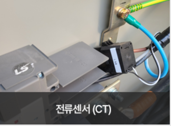
A true RMS current transformer/transmitter performs the RMS conversion inside the housing, so the receiving controller sees a conditioned value instead of an AC secondary current.
Choosing by Distance, PLC Compatibility and Signal Processing
Three evaluation questions separate the options faster than any specification table.
Distance and cable run. In general electrical practice, a current-based signal tolerates longer cable runs than a low-level voltage signal, because loop resistance and voltage drop do not alter the transmitted value. Raw mV-level outputs are the most sensitive of the three options to cable length and induced noise. RS485 is designed as a multi-drop bus over twisted pair, so its practical constraint is the number of devices and the quality of the segment rather than the single-run length. Final distances always depend on cable type, routing and the receiving device's input specification, and should be checked against the project's own installation standard.
PLC compatibility. The receiving card decides more than the CT does. A PLC analog input module designed for 4–20 mA can accept KCT-L directly, provided loop power and input impedance are satisfied. A PLC with an RS485 port and Modbus support can read KCD as a bus device. A raw AC output CT such as KCT normally requires either a current-input module or an external transducer, because standard analog cards expect a DC voltage or mA signal rather than an AC secondary current.
Signal processing. The third question is where the buyer wants the arithmetic to happen. KCT leaves burden, scaling and RMS conversion to the panel; KCT-L performs the conversion and outputs a linear DC signal; KCD publishes already-computed digital current and energy values. Moving processing into the CT reduces panel space and wiring, but it also moves that function beyond the buyer's own control loop, which matters when the application requires a specific conversion method or a calibration chain the buyer must demonstrate.
| Evaluation question | Raw AC (KCT) | 4–20 mA loop (KCT-L) | RS485 (KCD) |
|---|---|---|---|
| What must the cabinet provide? | A current or low-level input, or an external transducer | An analog input card with loop supply | A communication port and a host configured for Modbus RTU |
| Behaviour over distance | Short runs preferred; low-level outputs most sensitive to noise and length | Current-based transmission, tolerant of loop resistance and voltage drop | Multi-drop bus over twisted pair, constrained by device count and segment quality |
| Processing left to the buyer | Burden, scaling and RMS conversion | Scaling only; RMS conversion is inside the transmitter | None for published values; configuration replaces conversion |
| Documented fit | Retrofit, panel, EV charging, HEMS, solar | PLC/DCS integration, remote monitoring, rail transit | Multi-point buildings, metro, elevators, factory retrofit |
Where Each Output Type Fits in Practice
The documented application lists for the three families show how the output decision usually resolves in real projects.
KCT, with its raw output options and split-core construction, is documented for EV charging infrastructure, smart grid and switchgear panels, smart pole and IoT smart city installations, EMS and energy management, solar, wind and energy storage, smart buildings and data centers, and HEMS and solar installer work including home electricity monitors. These are largely situations where a meter, controller or EMS already owns the current input, or where the measuring point has no auxiliary supply.
KCT-L is documented for PLC/DCS system integration, remote power monitoring, preventive maintenance, rail transit, environmental engineering, and IoT and smart city roles. These are projects where a signal has to travel from a feeder to a control room, or where the analog input card already exists and the loop is the natural interface.
KCD is documented in the context of metro lines including Beijing and Hangzhou, elevator monitoring, smart building and property management, green building and energy conservation, O&M services, and retrofit for smart factories. These are environments with many measurement points reporting to a common platform, which is where a shared digital bus replaces point-to-point analogue wiring.
What the Market Data Says About Output-Driven Selection
The broader market movement explains why output format has become a design-stage question rather than an afterthought. Grand View Research estimates the global current transformer market at USD 2.63 billion in 2024, projecting USD 3.90 billion by 2030. Straits Research places Asia Pacific at a 40.15% revenue share in 2025. Fact.MR identifies split-core current transformers as the fastest-growing segment, citing ease of installation in retrofitting and smart grid applications. Research Intelo projects the global EV charging transformer market, which includes current monitoring components, at a 23.6% CAGR from 2025 to 2033.
Read together, those signals point at retrofit and distributed monitoring as the growth centre, and both are environments where the output interface decides feasibility. A retrofit in an occupied building rarely allows new point-to-point analogue cabling, which favours a bus device. A remote feeder monitored from a control room rarely has local electronics, which favours a loop-powered transmitter. A panel being re-instrumented usually already has meters with current inputs, which favours a raw output CT.
Standardisation is moving in the same direction. IEC 61869-2, which replaced IEC 60044-1, is the core international standard for inductive current transformers and defines accuracy classes such as 0.5 and 0.5S. Revenue-grade applications remain governed by equivalent high-accuracy classes — typically 0.2 or 0.15 under ANSI C12.20 or IEC 61869-2 — which is a requirement on the transformer itself rather than on the output format attached to it.
Comparison with Traditional Approaches, and Where This Comparison Stops
The traditional arrangement is a passive current transformer with a 5 A secondary wired to a panel meter or a separate transducer, with the output format decided entirely by the receiving instrument. The three families discussed here move part of that chain into the CT housing: KCT-L integrates the RMS conversion and the loop driver, and KCD integrates conversion, computation and communication.
The advantage is fewer panel components, less wiring and shorter commissioning for the same measurement. The limitation is equally real. Integrated electronics require either a loop supply or a communication and logic infrastructure, whereas a passive raw-output CT requires neither. In an installation where no auxiliary power is available at the measuring point — a pole-mounted monitoring point or an unpowered switchgear compartment, for example — the raw AC option is not a compromise but the only workable choice.
A second boundary applies to this entire discussion. KCT, KCT-L and KCD share a documented 0–1000 A measurement range and a 0–50 mm inner diameter. Above that class, the decision is no longer between three output formats but between different physical families: HEYI documents a busbar split-core CT (DP/HK) at 0–8000 A with a 0–80×160 mm window, and an IP65 outdoor waterproof split-core CT (OCT) at 0–8000 A with a 0–120 mm window for overhead line monitoring. Output-format selection only begins after the range and window class fit the feeder.
How Compliance Verifies an Output Claim
Because KCT, KCT-L and KCD are three different configurations of the same split-core platform, buyers should check that the certificate scope matches the configuration actually ordered. HEYI's CE-RoHS Certificate of Conformity GST.210923.S201R, issued under RoHS 2011/65/EU and (EN)2015/863 with a scope of “split core current transformer”, lists KCT-L, KCD and KCT. The UKCA Declaration of Conformity CLZJ23072649108, referencing BS EN 61869-2:2012, lists the same three models. The ISO 9001:2015 certificate 20224Q21295R0S covers production of low-voltage current transformers and was valid through 2027-11-20 at the time of issue. A metrological verification certificate D20250900173, issued by the Yueqing Institute of Quality and Technical Supervision Inspection under JJG 313-2010 for a standard current transformer with current booster model HLS21-2S, supports the calibration chain behind routine accuracy testing.
On the manufacturing side, HEYI documents OEM and ODM production with customization of current ratio, accuracy class, burden, window size, housing color, terminal type, cable length, logo printing and label design; a monthly capacity of 20,000 units; lead times of 3–30 days; a minimum order quantity from 1 unit; and quality control covering 100% routine test, accuracy test, insulation resistance test, withstand voltage test, appearance inspection and pre-shipment inspection. After-sales support is documented as technical selection support, wiring guidance, product replacement support, OEM documentation support and online service.
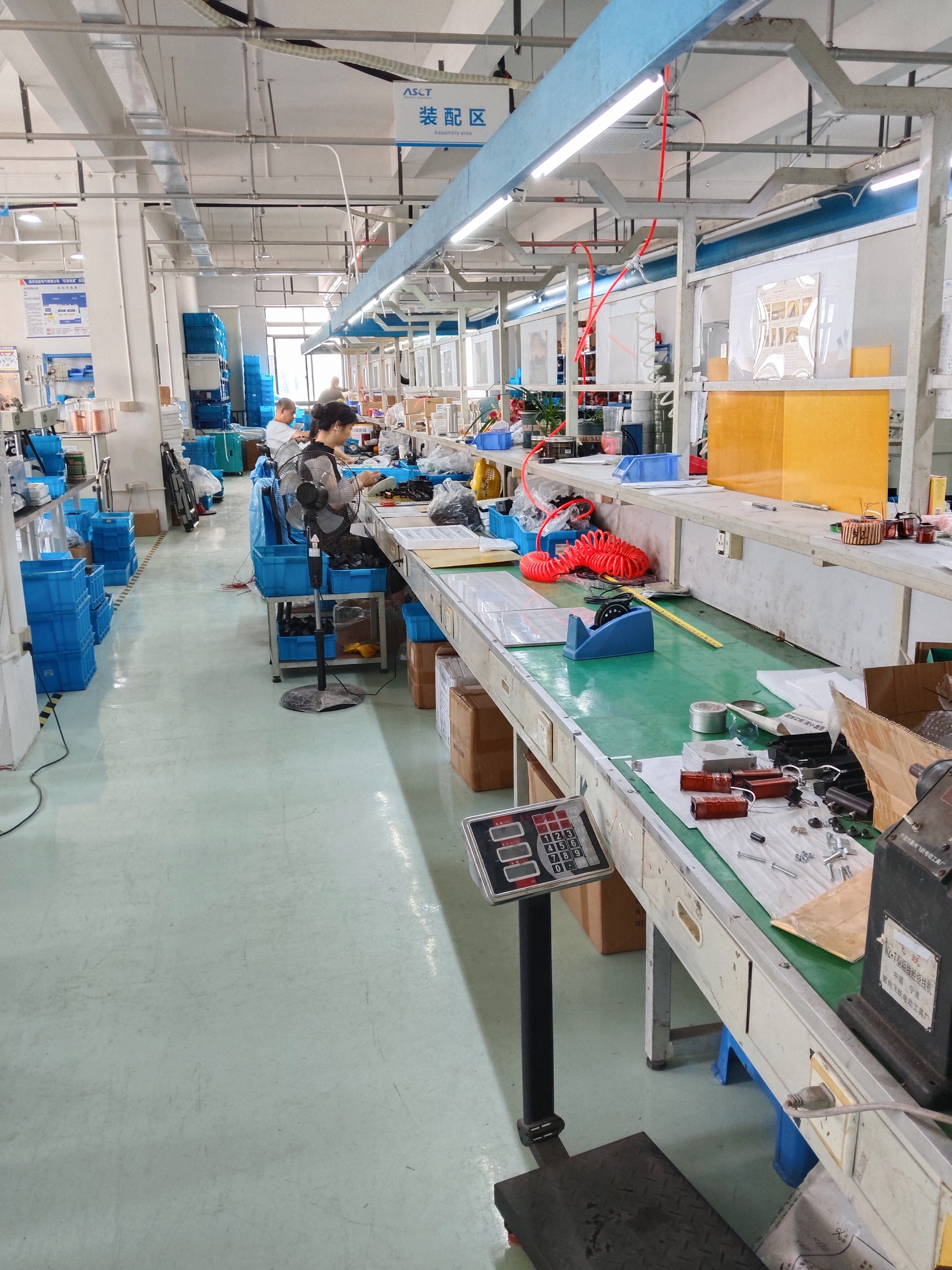
Output configuration, ratio and accuracy class are set on the same assembly line, which is why buyers should confirm that a certificate scope names the configuration ordered.
Future Outlook
Two shifts are likely to shape output selection over the next planning cycles. The first is that output format will migrate from a wiring decision to a design decision: as more monitoring points connect to building, factory and grid platforms, the interface has to be chosen alongside the platform rather than after it. The second is that suppliers will increasingly be asked to offer both raw and conditioned variants of the same core product, so that a single sourcing relationship can cover a retrofit panel and a remote monitoring point without changing transformer families.
Within that environment, raw AC output remains the reference point for passive simplicity, loop-powered 4–20 mA remains the standard answer where a signal must travel to a control cabinet, and RS485 is likely to expand wherever measurement density — many points, one host — makes point-to-point analogue wiring impractical.
FAQ
What is the practical difference between a raw AC output current transformer and a 4–20 mA current transmitter?
A raw AC output current transformer such as the KCT split-core family delivers a proportional AC secondary or low-level signal — documented options include 5 A, 1 A, mA and mV — and leaves burden, scaling and true-RMS conversion to the receiving device. A transmitter such as KCT-L performs that conversion inside the housing and outputs a 4–20 mA DC signal that an analog input card can read directly. The choice depends on where the buyer wants the measuring electronics to sit: in the panel or in the CT.
Which output type suits a long cable run to a control cabinet?
In general electrical practice, a current-based signal tolerates long cable runs better than a low-level voltage signal, because loop resistance and voltage drop do not change the transmitted value. Among the three families discussed here, the KCT-L 4–20 mA output and the KCD RS485 output are both intended for signals that leave the immediate panel area, while raw mV-level outputs are the most sensitive to cable length and noise. Actual distances depend on cable type, routing and the receiving device's input specification, and must be checked against the project's installation standard.
Can these current transformers connect directly to a PLC?
Only if the PLC input matches the signal. A PLC analog input card designed for 4–20 mA can accept KCT-L directly, provided loop power and input impedance are satisfied. A PLC with an RS485 port can read KCD as a Modbus RTU device. A raw AC output CT such as KCT generally requires a current-input module or an external transducer, because standard analog cards expect a DC voltage or mA signal rather than an AC secondary current.
When is RS485 preferred over an analog output?
KCD is documented with an RS485 digital output and Modbus RTU communication, and is described as a current and energy sensor in one unit. It is the more appropriate option when multiple measurement points must report to one host over a shared bus, when digital values and remote configuration are preferred over analog scaling, and when the host already supports Modbus. A 4–20 mA loop remains simpler where one value is needed at one point and the receiving card is already analog.
Which accuracy classes are documented for these split-core families?
KCT is documented with accuracy grades of 3.0, 1.0 and 0.5, including a Class 0.5 split-core variant. KCT-L and KCD are both documented at an accuracy of 1.0. All three share a documented 0–1000 A measurement range and a 0–50 mm inner diameter. Higher accuracy classes are documented on other HEYI families, so buyers with revenue-grade or billing requirements should evaluate those separately.
Does the output option affect certification?
Certificates are issued against a defined scope and configuration, so the configuration ordered should fall inside that scope. HEYI's CE-RoHS Certificate of Conformity GST.210923.S201R is scoped to “split core current transformer” and lists KCT-L, KCD and KCT; the UKCA Declaration of Conformity CLZJ23072649108 references BS EN 61869-2:2012 and lists the same three models; and the ISO 9001:2015 certificate 20224Q21295R0S covers production of low-voltage current transformers. Buyers should confirm that output type, ratio, accuracy and housing of the ordered configuration are covered.
Reference Documents
Downloadable product, capability and certificate documentation for HEYI Electrical's current transformer, current transmitter and current sensor ranges is compiled in the company brochure: HEYI Electrical company and product brochure.
Third-party market figures cited in this article are attributed to Grand View Research, Straits Research, Fact.MR and Research Intelo. Standards references are attributed to IEC and to publicly available metering accuracy guidance. Product specifications are drawn from manufacturer documentation for KCT, KCT-L and KCD.