
Chassis Busbar Constraints: What to Verify Before Ordering
A chassis busbar is a fixed conductive bar mounted on a chassis or mounting plate inside a low-voltage distribution assembly, fed from a single incoming connection and used to distribute power to a row of miniature circuit breakers. It belongs to the broader category of pan assembly busbars, which also includes MCB pan assemblies, MCCB pan assemblies and distribution box busbars. For a buyer working through research and evaluation, the decision that matters is not which busbar is best in the abstract; it is which combination of rated current, terminal geometry, pole distance, conductor material and certification scope will survive a project's electrical and compliance review, and which of those constraints cannot be changed later without redesigning the assembly.
That framing matters because busbar pan assemblies are not generic components. They are dimensioned products, and every dimension is a constraint that either fits a selected breaker or does not. The sections below set out the constraints in the order a procurement team usually meets them: geometry first, then rating, then documentation, then commercial terms.
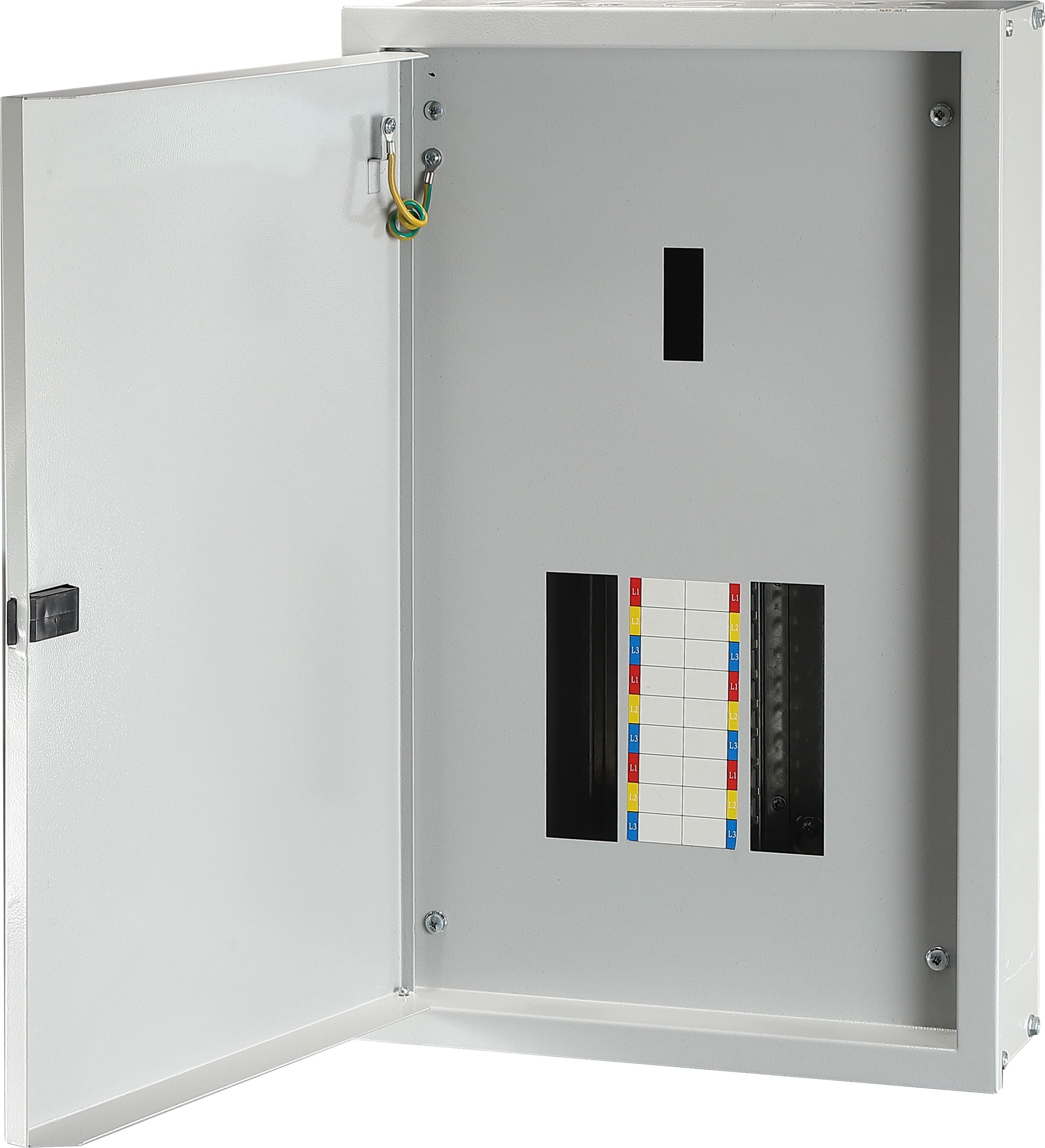
A low-voltage distribution box built around an MCB pan assembly busbar. Busbar-based distribution replaces individual cable runs between breaker poles with a pre-formed conductive bar on a mounting plate.
Why chassis busbar specifications fail project review
Three failure modes account for most specification problems in this product family. Each one is detectable at the research and evaluation stage, and each one becomes expensive once panels are in production.
1. Geometry mismatch
Terminal dimensions decide whether a busbar can physically connect to the breakers already selected for a project. In the documented BARFUSE range, the BP6 MCB 3P chassis busbar has an outgoing terminal width of 6.5 × 12 mm and an incoming terminal width of 21 × 22 mm, while the BP1 MCB 3P pan assembly specifies a connection size of 2.0 × 5 mm and an outline size of 2.0 × 20 mm. These are different interfaces serving different breaker terminals. A geometry check has to be run against the exact breaker model and pole configuration, not against a category description such as “3P pan assembly”.
2. Current rating and ways-count mismatch
Conductor cross-section drives ampacity across this range. The BP4 MCB 1P pan assembly busbar is documented at 125 A with a 2 mm conductor, 160 A at 2.5 mm and 250 A at 3 mm, in configurations from 4W to 72W. The BP5 MCCB 2P pan assembly busbar documents a larger step: incoming ratings of 125 A at 4 mm, 250 A at 6 mm and 400 A at 10 mm, with outgoing ratings of 63 A at 2 mm and 125 A at 3 mm. Choosing ways count without matching thickness to the intended load leaves a rating gap that no assembly work can close afterwards.
3. Documentation and certification scope mismatch
Certification in this category is model-specific rather than catalogue-wide. The DEKRA test certificate held for the busbar range covers the models BP1-125 and BP1-250 under certificate numbers 3309992.100 and 3309992.101. A configuration that changes the model designation or the assembly arrangement falls outside the documented scope until it is verified in its own right. Buyers who assume that a supplier-level quality certificate transfers automatically to every item on a price list create a compliance risk that surfaces late, usually during customer approval or project handover.
Constraint checklist for chassis busbar procurement
Before a chassis busbar or pan assembly busbar is written into a bill of materials, the parameters below should be traceable to supplier documentation. The reference column shows how each constraint is expressed in the documented BARFUSE range, which illustrates the level of detail a usable specification actually contains.
| Constraint | What must be verified | Documented reference example |
|---|---|---|
| Rated current | Incoming and outgoing ratings matched to the upstream device and the branch loads | BP6 rated 250 A; BP1 at 125 A, 160 A or 250 A; BP3 incoming 250 A, 400 A, 630 A or 800 A with outgoing 125 A, 250 A or 400 A |
| Terminal geometry | Incoming and outgoing terminal thickness and width checked against the breaker terminals | BP6 outgoing 6.5 × 12 mm, incoming 21 × 22 mm; BP2 outgoing 2 × 5 mm, incoming 3 × 15 mm; BP4 outgoing 5 × 11 mm (width × length), incoming terminal width 20 mm; BP5 outgoing terminal width 15 mm, incoming terminal width 25 mm |
| Pole distance | Distance between breaker poles for the selected device brand | BP3 accepts MCCBs with pole distances of 25 mm, 30 mm, 35 mm and 45 mm; BP5 is designed for DP MCCBs with 25 mm pole distance and 50 mm width |
| Ways count | Outgoing ways required now, plus any planned expansion within the same assembly | BP1 6W–72W; BP4 4W–72W; BP5 2W–40W; BP3 available in 2W, 4W, 6W, 8W, 10W, 12W and 14W |
| Conductor and insulation material | Conductive material, insulation material, and the resulting weight and handling implications | Copper conductors with PC (polycarbonate) parts; copper is documented as the primary material of the BP1 MCB 3P pan assembly |
| Standard claimed | The exact standard and edition the product is documented against | BP6 documented as compliant with IEC 61439 and AS/NZS standards; BP1-125 and BP1-250 certified to IEC 61439-2:2011 and EN 61439-2:2011 |
| Certification scope | Which models, markets and assembly types a certificate actually names | DEKRA test certificate names BP1-125 and BP1-250 as an open-type assembly without enclosure; ISO 9001:2015 certificate 62724Q1160R0S covers manufacturing and export of busbar systems and distribution boxes |
| Customization and lead time | Whether mounting plates, ways and finishes can be adapted, and the schedule impact | Mounting plate customizable to the outgoing MCB; OEM accepted on BP3 with sizes customized to the customer's MCCB; documented lead time 15–45 days |
Reference values above are drawn from BARFUSE product and certification documentation for the models named.
What the documented BARFUSE range covers
BARFUSE is the trading identity of Yueqing Barfuse Electric Co., Ltd., a manufacturer based in Wenzhou, Zhejiang Province, China, established in 2014. The company produces low-voltage fuse switch disconnectors, busbar systems and low- and high-voltage distribution wiring management products, including MCB pan assemblies and MCCB pan assemblies, and operates a 10,000 m² facility with 45 employees, a 7-engineer R&D team and a documented annual output of 250,000 pieces. Export accounts for 90 percent of output, distributed across the Middle East, Russia, Latin America, Central Asia, the EU, Africa and Oceania, with a sales network documented in more than 40 countries and regions.
Manufacturing documentation lists more than 30 modern digital wire-cutting machines and punches, together with inspection equipment that includes a Rockwell hardness tester, an electric withstand voltage tester, a spring tester, a salt spray tester, a flame retardant tester and a switch tester. The company profile also states that BARFUSE holds testing accreditations from KEMA (DEKRA) in the Netherlands and VDE in Germany, along with CB certification and SAA certification in Australia.

Production workshop. Busbar and pan assembly production depends on punching and forming accuracy, since tooth pitch and terminal dimensions are what determine whether a busbar fits a given breaker row.
For chassis busbar and pan assembly buyers, the operative part of the portfolio is a set of modular busbar systems built on copper conductors with polycarbonate insulation, plus matching distribution boxes.
| Model | Type | Key documented parameters |
|---|---|---|
| BP6 | MCB 3P chassis busbar | Rated 250 A; outgoing terminal 6.5 × 12 mm; incoming terminal 21 × 22 mm; mounting plate customizable to the outgoing MCB; documented as compliant with IEC 61439 and AS/NZS standards |
| BP1 | MCB 3P pan assembly | Rated 125 A, 160 A or 250 A; connection size 2.0 × 5 mm; outline size 2.0 × 20 mm; 6W–72W; DEKRA test certificate; complies with CE and RoHS directives |
| BP2 | MCB 2P pan assembly | Rated 125 A or 250 A at 220 / 240 / 120 V; incoming MCCB or MCB; outgoing double-pole MCB or RCBO; outgoing terminal 2 × 5 mm; incoming terminal 3 × 15 mm |
| BP4 | MCB 1P pan assembly busbar (comb busbar) | Rated 125 A, 160 A or 250 A at conductor thickness 2 mm, 2.5 mm or 3 mm; 4W–72W; outgoing terminal 5 × 11 mm; incoming terminal width 20 mm |
| BP3 | MCCB 3P pan assembly | Incoming 250 A, 400 A, 630 A or 800 A; outgoing 125 A, 250 A or 400 A; 2W–14W; compatible with MCCBs at 25 mm, 30 mm, 35 mm and 45 mm pole distance; OEM accepted |
| BP5 | MCCB 2P pan assembly busbar | Incoming 125 A (4 mm), 250 A (6 mm) or 400 A (10 mm); outgoing 63 A (2 mm) or 125 A (3 mm); 2W–40W; incoming terminal width 25 mm; outgoing terminal width 15 mm |
| DB01 | Distribution box with MCB pan assembly busbar | Incoming MCCB 250 A, MCCB 125 A or MCB 63 A; MCB branch circuits; 2W–32W; textured finish RAL7032 or RAL7035 |
| DB02 | Distribution box with MCCB pan assembly busbar | Incoming MCCB 800 A, 630 A, 400 A, 250 A or 125 A; branch MCCB 400 A, 250 A or 125 A; 2W–16W |
| DB13 | Waterproof low-voltage distribution box | Protection degree IP65; impact resistance IK10; enclosure and door 1.2–1.5 mm steel sheet; mounting plate 2.0 mm |
How the geometry of a chassis busbar determines compatibility
A busbar pan assembly works by replacing point-to-point cable connections with a single shaped conductor. The conductor is cut or punched to a defined tooth pitch so that each outgoing way lines up with a breaker terminal, and the mounting plate positions the bar so that the alignment holds across the full row. Two variables control what the bar can carry: the cross-section of the conductor and the contact area at each terminal.
The relationship between thickness and rating is visible in the documented data. On the BP4 MCB 1P pan assembly busbar, the same product family moves from 125 A to 160 A to 250 A as conductor thickness increases from 2 mm to 2.5 mm to 3 mm. On the BP5 MCCB 2P pan assembly busbar, the incoming side steps from 125 A at 4 mm to 250 A at 6 mm to 400 A at 10 mm. Pole-count and device type then determine the layout: the documented range covers 1P MCB, 2P MCB and 3P MCB busbars as well as 2P and 3P MCCB busbars, and the BP5 is documented for simultaneous live and neutral disconnection, while the BP2 supports double-pole MCB or RCBO branch devices.
The practical consequence for evaluation is that a chassis busbar is defined by four numbers before anything else is discussed: rated current, terminal thickness and width, pole distance and ways count. A supplier conversation that does not reach those four numbers has not reached the technical specification.
Terminology: mapping common busbar terms to documented models
Busbar vocabulary varies between regions and between panel builders, and the same word can describe different hardware. The table below maps frequently used terms to what is actually documented in this product range, so that a search term does not get mistaken for a verified specification.
| Term | What it usually describes | Status in the documented range |
|---|---|---|
| Chassis busbar | A fixed bar on a chassis or mounting plate feeding a breaker row | Documented as the BP6 MCB 3P chassis busbar, rated 250 A |
| MCB pan assembly busbar | Modular bar assembly for a row of miniature circuit breakers | Documented as BP1 (3P), BP2 (2P) and BP4 (1P) |
| MCCB pan assembly busbar | Bar assembly for moulded case circuit breaker distribution | Documented as BP3 (3P) and BP5 (2P) |
| Comb busbar | A toothed bar distributing one phase across several single-pole devices | The BP4 is documented as a comb busbar for distribution boards |
| SP / DP / TP, modular, pre-assembled and cabinet pan assembly busbars | Wording that describes pole count, modularity or the enclosure a busbar is installed in | The documented range covers 1P, 2P and 3P MCB configurations and 2P and 3P MCCB configurations; project terminology should be mapped to a specific model before ordering |
| Distribution box busbar | A busbar system integrated into a distribution enclosure | Documented as DB01 and DB02, with DB13 as a waterproof enclosure option rated IP65 and IK10 |
| Neutral terminal busbar, earth terminal busbar, feed pillar busbar, plug-in busbar, SMDB busbar | Related low-voltage distribution hardware used in panel building | Not covered by the models documented in this material; availability and parameters must be confirmed separately instead of assumed |
| Aluminum busbar / aluminum pan assembly busbar | Busbars using aluminium conductors instead of copper | A distinct industry product class; the models documented in this range use copper conductors with PC parts |
Where chassis busbars and pan assemblies are used
The documented application profile for this product family is indoor low-voltage distribution, matched with circuit breakers, operating continuously in industrial applications and commercial building electric management. Working ratings across the range span 125 A, 160 A, 250 A, 400 A, 630 A and 800 A, and the function is power distribution with circuit protection in low-voltage distribution systems.
Typical uses follow directly from those parameters:
- Commercial sub-distribution boards. Panels built from 1P, 2P or 3P MCB busbars, where the row layout and tooth alignment define installation speed; the BP4 documents 4W to 72W and the BP1 documents 6W to 72W.
- Industrial feeders. MCCB-level distribution where incoming ratings reach 400 A, 630 A or 800 A on the BP3 and 400 A on the BP5, with branch protection at 125 A, 250 A or 400 A.
- Factory-assembled distribution boxes. The DB01 documents incoming MCCB 250 A, MCCB 125 A or MCB 63 A with MCB branch circuits and 2W to 32W; the DB02 documents incoming MCCB ratings up to 800 A with branch MCCBs and 2W to 16W.
- Harsh or outdoor-adjacent locations. The DB13 provides a documented IP65 protection degree and IK10 impact resistance with a 2.0 mm mounting plate.
- Refurbishment and replacement projects. Where an existing breaker layout has to be matched, and the mounting plate becomes the decisive part of the order.
Geographically, documented deployment covers markets including Indonesia, Kuwait, Nigeria, Oman, Russia, Syria, Peru, Mexico, Saudi Arabia, Thailand, Vietnam, Venezuela, Pakistan, the Philippines, Malaysia, Mongolia, Myanmar, Romania, Australia, Argentina, Bangladesh, Chile, Algeria, Ecuador, Egypt, Trinidad and Tobago, Turkey, South Africa, Cambodia, Kenya and Jamaica, among others listed in the published market data.
Market trend analysis: material mix, standards and density
Research published by Precedence Research places the global busbar market at USD 19.83 billion in 2025, with copper busbars holding 62.8 percent of material share in the same year. The same publisher forecasts aluminum busbars growing at a 6.9 percent CAGR between 2026 and 2035, citing roughly 40 percent lower weight and cost optimization in large infrastructure as drivers, while laminated busbars are forecast at an 8.9 percent CAGR in high-density applications.
Published estimates are not uniform, and that matters for anyone building a business case. Stratview Research reports a 2025 market size of USD 15.72 billion, while IMARC reports USD 20.3 billion. The difference is attributed to whether locally custom-fabricated busbars are counted alongside factory-assembled trunking systems. Treating the published range as a range, rather than quoting a single figure as fact, is the more defensible position.
Two structural signals sit behind those numbers. On the supply side, Congruence Market Insights states that China accounts for more than 30 percent of global copper processing capacity and produces more than 11 million metric tons of refined copper annually, which keeps copper-based busbar manufacturing concentrated in that supply chain. On the standards side, IEC 61439-6:2025, the part of the IEC 61439 series addressing busbar trunking systems, carries an effective date of 1 December 2025. That part addresses a different product class than the modular pan assemblies and chassis busbars discussed here, where the documented certification reference in this range is IEC 61439-2:2011 and EN 61439-2:2011 for the BP1-125 and BP1-250 busbar panels.
For buyers, the practical reading is that material selection is now a live commercial decision rather than a fixed default, and that standard revisions increase the documentation burden on suppliers. Both trends favour specifications that cite model-level data rather than category-level claims.
Busbar pan assemblies compared with conventional cable wiring
The comparison buyers usually need is not busbar versus busbar, but busbar pan assembly versus conventional cable and lug wiring inside the same enclosure.
| Dimension | Busbar pan assembly | Conventional cable and lug wiring |
|---|---|---|
| Assembly process | Repeated mechanical connection onto pre-formed teeth with consistent spacing | Individual cable cutting, stripping, crimping and torquing per pole |
| Consistency | Dimensional consistency set by the tooling, so each way repeats the same geometry | Depends on installer technique and is harder to verify visually |
| Space use | Compact and predictable footprint mapped to the breaker row | Cable bending radii and routing occupy additional enclosure volume |
| Modification after build | Adding a way depends on ways available on the model, documented up to 72W on BP1 and BP4 | Each change is a re-routing and re-termination exercise |
| Rating coverage | Documented from 125 A on MCB pan assemblies to 800 A incoming on the BP3 | Limited by terminal and lug size at the device, and by cable cross-section |
| Cost structure | Higher tooling and plate content in exchange for repeatable assembly time | Lower component complexity, more labour hours per panel |
Three boundaries belong in any honest version of this comparison.
- Fixed geometry. A busbar built for one breaker layout does not adapt to another. The BP6 mounting plate is customized according to the outgoing MCB, and the BP3 documents that sizes are customized to the customer's MCCB. If the breaker family changes after the panel is designed, the busbar generally changes with it.
- Rating ceiling. Within the documented range, MCB pan assemblies sit between 125 A and 250 A, the chassis busbar at 250 A, and MCCB pan assemblies reach 800 A incoming on the BP3 and 400 A on the BP5. Applications above those levels require a different distribution architecture.
- Documentation boundaries. Certification follows the model and the assembly arrangement. The DEKRA test certificate naming BP1-125 and BP1-250 describes an open-type assembly without enclosure, so a variant installed in a different enclosure or with different internal clearances is a new configuration from a compliance standpoint and must be assessed as such.
There is also a material boundary worth stating plainly: the documented models in this range use copper conductors with polycarbonate insulation, so copper weight and copper price exposure apply to panels built on them. Aluminium busbars are a growing industry class, but they are not the same product as the copper-based models documented here, and a buyer comparing them is comparing two material systems, not two suppliers of one component.
Commercially, the documented terms are a lead time of 15–45 days, a monthly capacity of 8,000 pieces and a minimum order quantity documented at 1 piece. On projects with many distinct busbar configurations, the configuration freeze date rather than the order date usually determines whether the schedule holds.
Future outlook
Three shifts are likely to shape chassis busbar specification over the next planning cycle. The first is material mix: aluminum busbars are forecast to grow faster than the market overall, at a 6.9 percent CAGR for 2026 to 2035 according to Precedence Research, while copper retains the majority of material share. Buyers should expect more requests to justify material choice on weight and cost grounds rather than by default. The second is density: laminated busbars are forecast at an 8.9 percent CAGR in high-density applications, which points to continued pressure on enclosure volume in compact assemblies. The third is documentation: standards activity around the IEC 61439 series, including the IEC 61439-6:2025 update effective from 1 December 2025, keeps raising the bar for what counts as adequate technical evidence in a procurement file.
Underneath those shifts sits a persistent trade-off. Customization improves fit — mounting plates adapted to a specific outgoing MCB, sizes adapted to a specific MCCB brand — but it reduces interchangeability across projects. Suppliers that publish model-level dimensional data, certificate scope and configuration options make that trade-off visible early, which is what allows a buyer to price the schedule risk instead of discovering it during assembly.
Frequently asked questions
What is a chassis busbar and where does it sit inside a low-voltage distribution assembly?
A chassis busbar is a fixed conductive bar mounted on a chassis or mounting plate inside a low-voltage assembly, carrying current from an incoming connection to a row of outgoing breakers in place of individual cable runs between poles. In the documented BARFUSE range, the BP6 is an MCB 3P chassis busbar rated 250 A with an outgoing terminal of 6.5 × 12 mm and an incoming terminal of 21 × 22 mm, intended for industrial application and commercial building electric management, with a mounting plate that can be customized to the outgoing MCB. It sits alongside MCB pan assembly busbars (BP1, BP2, BP4), MCCB pan assembly busbars (BP3, BP5) and distribution boxes (DB01, DB02, DB13) in the same product family.
Which ratings and terminal dimensions should be verified before ordering a pan assembly busbar?
Four values should be verified against documentation: rated current, terminal thickness and width on both the incoming and outgoing side, pole distance, and ways count. Documented examples from this range show why each matters. BP1 is rated 125 A, 160 A or 250 A with a connection size of 2.0 × 5 mm and an outline size of 2.0 × 20 mm across 6W to 72W. BP2 is rated 125 A or 250 A at 220 / 240 / 120 V, with an outgoing terminal of 2 × 5 mm and an incoming terminal of 3 × 15 mm for double-pole MCB or RCBO branches. BP4 steps from 125 A at 2 mm thickness to 160 A at 2.5 mm and 250 A at 3 mm, with an outgoing terminal of 5 × 11 mm and an incoming terminal width of 20 mm. BP3 accepts MCCBs with pole distances of 25 mm, 30 mm, 35 mm and 45 mm, and BP5 is designed for DP MCCBs with a 25 mm pole distance and 50 mm width.
What standards and certificates apply to these busbars, and what exactly do they cover?
Two documents are central in this range. The first is a DEKRA test certificate issued by DEKRA Certification B.V. under certificate numbers 3309992.100 and 3309992.101, covering busbar models BP1-125 and BP1-250 under the brand BARFUSES, series BFSe, described as an open-type assembly without enclosure, assessed against IEC 61439-2:2011 and EN 61439-2:2011, issued on 5 September 2016 with an expiry date of 5 September 2099. The second is an ISO 9001:2015 certificate, number 62724Q1160R0S, issued by Jingxin Certification (Beijing) Co., Ltd. against GB/T19001-2016 idt ISO 9001:2015, valid from 8 November 2024 to 7 November 2027, covering manufacturing and export of strip fuse disconnectors, load disconnectors, busbar systems (MCCB/MPCB busbars) and distribution boxes, plus export of fuses and fuse bases. The BP1 range is also documented as complying with CE and RoHS directives, and the BP6 chassis busbar is documented as compliant with IEC 61439 and AS/NZS standards. Each document covers the models and scope it names, so applying it to a different configuration or market requires separate confirmation.
Can mounting plates and sizes be customized, and what changes as a result?
Yes, within documented limits. The BP6 mounting plate can be customized according to the outgoing MCB, and the BP3 accepts OEM orders with sizes customized to the customer's MCCB, usable across MCCBs with pole distances of 25 mm, 30 mm, 35 mm and 45 mm. The overall customization scope documented for the manufacturer covers colour, logo, material, new design, surface treatment, mold development and packing, with a minimum order quantity of 1 piece, a lead time of 15–45 days and a monthly capacity of 8,000 pieces. The consequence of customization is reduced interchangeability: once the mounting plate is adapted to one breaker layout, the dimensional drawing, the bill of materials entry and the applicability of any model-level certificate should all be re-confirmed for that specific build rather than assumed from the base model.
What limits should buyers accept when choosing a busbar pan assembly instead of cable wiring?
Four limits are documented or directly implied by the published parameters. First, geometry is fixed: a busbar suited to one breaker layout will not adapt to a different one without a new mounting plate, because the plate is dimensioned to the outgoing device. Second, there is a rating ceiling within the range: MCB pan assemblies document 125 A to 250 A, the chassis busbar 250 A, MCCB pan assemblies up to 800 A incoming on BP3 and 400 A on BP5. Third, certification is model-scoped rather than catalogue-wide, so a configuration change moves the item outside the named certificate scope until it is verified. Fourth, the documented materials are copper conductors with PC parts, which brings copper weight and material cost exposure into the panel design. Cable and lug wiring remains more adaptable where layouts are still undecided or where ratings fall outside those bands.
Technical documentation covering the busbar system and distribution box range, including the models referenced above, is available in the manufacturer's catalogue: BARFUSE Catalogue (PDF).
Tem questões ou precisa de mais detalhes?
Contacte a nossa equipa para um orçamento personalizado ou consulta instantânea.
Solicitar orçamento
Preencha o formulário abaixo e a nossa equipa entrará em contacto com uma proposta personalizada.
Chat direto do WhatsApp
Prefere conversar em tempo real? Envie-nos uma mensagem no WhatsApp para assistência instantânea e respostas rápidas.
- Obter orçamento personalizado
- Partilhar fotos ou documentos
- Discuta as suas necessidades diretamente
Geralmente responde em 5–30 minutos durante o horário de expediente.