
Connector Terminal RFQ FAQ: Wire Range, Insertion Force, Plating
Connector Terminal RFQ FAQ: Wire Range, Insertion Force, Plating
An automotive connector terminal is bought on a drawing, not on a catalogue page. The drawing carries the numbers that decide whether the part crimps cleanly, mates at a workable force and survives the harness build: conductor range, mated insertion and extraction force, pre-tin thickness, contact alloy, compliance documentation and reel quantity. When one of those numbers is missing from an OEM RFQ, the gap usually surfaces at the crimp press or at end-of-line electrical test rather than at quotation stage.
This reference works through the six parameters that define one terminal family for a 0.25–0.35 mm² automotive wire connector — a mated insertion and extraction force of 0.5–4 N, pre-tin thickness of 2–6 µm, CuNi3Si contact and SUS301 spring construction, a RoHS declaration and 5,000-piece reel packaging — and sets out how a buyer checks each value against the physical sample. It is written for the evaluation-to-execution stage, where the specification is already fixed and the remaining risk is whether the delivered part matches it.
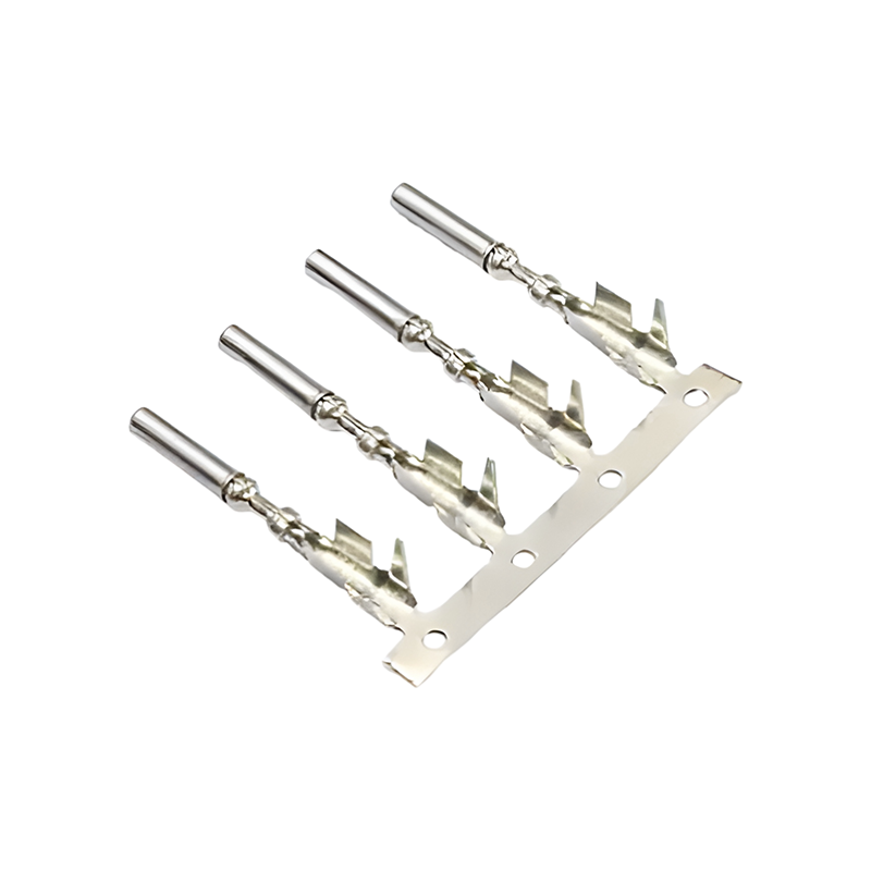
Why the RFQ carries more weight than the datasheet
The terminal is one half of a crimp. Final electrical and mechanical performance belongs to the combination of terminal, wire and crimp tooling, so a terminal that meets its own drawing can still fail in a harness if the wire sits outside the barrel window or the crimp height is set for a different insulation diameter. The RFQ is the only document that binds all three together, which is why parameter confirmation belongs there rather than in a supplier's catalogue footnote.
Two consequences follow. A terminal quoted without a stated wire range is not comparable to one quoted with it, because the crimp barrel geometry differs. And a parameter measured under unstated conditions cannot be accepted or rejected — mated force in particular changes with engagement speed, plating and sample conditioning. Both points are worth settling in writing before price negotiation begins.
The six parameters at a glance
A complete terminal RFQ for this application fixes the following values. The table restates them in the form a buyer can check against a sample and a first-article report.
| Parameter | Value in this RFQ | What must be confirmed | Why it matters |
|---|---|---|---|
| Conductor range | 0.25–0.35 mm² | Conductor cross-section, insulation outer diameter, strip length, crimp height | Decides whether the barrel crimps the wire the harness actually uses |
| Mated insertion / extraction force | 0.5–4 N | Direction, engagement speed, sample conditioning, cycle number | Sets both contact engagement and assembly ergonomics |
| Pre-tin thickness | 2–6 µm | Measurement method and location, matte or reflowed tin, underplate | Controls corrosion margin, insertion friction and solderability |
| Contact and spring material | CuNi3Si contact, SUS301 spring | Mill certificate, which element carries which alloy, lot traceability | Governs spring retention and resistance stability over temperature |
| Compliance | RoHS declaration | Substance list, test-report scope, part numbers, validity dates | Separates product compliance from management-system certification |
| Reel packaging | 5,000 pieces per reel | Tape pitch and width, orientation, splice policy, leader and trailer | Affects reel changes, splice points and line uptime |
Wire range 0.25–0.35 mm²: what the crimp barrel actually accepts
A 0.25–0.35 mm² callout describes the conductor, not the finished wire. The barrel must also accept the insulation outer diameter, and on a sealed connector a separate seal has its own wire window. An RFQ that quotes only the cross-section leaves two variables open: the insulation diameter that sets strip length and crimp width, and the seal bore that decides whether the assembly is watertight.
Ask for four numbers rather than one — conductor range, insulation outer diameter range, strip length and crimp height — and add the crimp pull-out force with its test method. Pull-out is the usual acceptance criterion at incoming inspection, and it fails first when the barrel has been sized for a different strand count.
Unit habits cause avoidable errors here. Metric drawings specify mm², while harness drawings from North American programmes often carry AWG. The two systems map closely but not identically, so a 0.25–0.35 mm² window should be converted explicitly on the RFQ rather than inferred by habit from the nearest AWG size. A terminal accepted on an approximate conversion is a terminal accepted outside its declared range.
Mated insertion and extraction force 0.5–4 N
Insertion force is the force required to mate a male and female terminal; extraction force is the force required to separate them. Both are properties of the mated pair, measured on the contact system, and neither equals terminal-to-housing retention — the force that keeps a crimped terminal seated in its cavity. Treating the two as one number is a common RFQ error, and they need separate lines on the drawing.
The 0.5 N floor exists because a contact pair needs enough normal force to engage and wipe through surface film at the interface. The 4 N ceiling protects the assembly: high per-circuit force accumulates across a multi-pin automotive connector housing, raises the risk of bent terminals or damaged locking features during mating, and pushes insertion effort onto the line operator. The window is therefore a range to be held, not a target to be minimised.
Force numbers are only comparable when the measurement conditions travel with them. Fix the engagement direction and speed, the number of conditioning cycles, whether the sample is lubricated or dry, plated or as-received, and whether measurement is taken on a loose terminal pair or on a crimped assembly seated in its housing. A supplier reporting 0.5–4 N without those conditions has reported a number, not a specification.
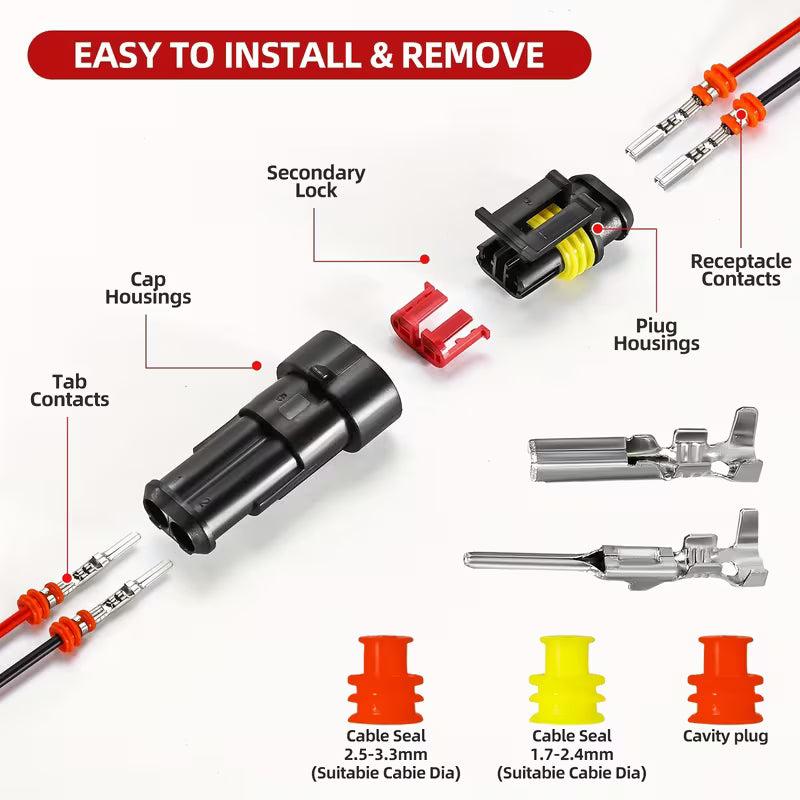
Pre-tin 2–6 µm: thickness, method and boundary
Pre-tinning deposits tin on the base metal before crimping. Within 2–6 µm it provides a corrosion margin at the contact zone, a controlled friction level during mating, and solderability where the terminal is later joined to a PCB or splice. The floor matters because stamped edges and burrs are where coverage thins first; the ceiling matters because tin is soft, and a very thick deposit can cold-flow under contact load, smear during mating and add cost without adding protection.
Thickness needs a stated measurement method. X-ray fluorescence is fast and non-destructive but reports an average across the excited spot, including edges and curvature. Cross-section examination of a mounted sample gives local thickness at the actual contact zone and shows any underplate. An RFQ that names only the range and not the method can produce two fully compliant certificates for two parts that behave differently in the application.
One further distinction belongs on the drawing: matte tin and reflowed tin behave differently in insertion and are not interchangeable on a quotation. Where the corrosion or mating-cycle requirement exceeds what a 2–6 µm tin deposit supports, nickel underplate or a gold contact finish are the usual alternatives — both appear among the plating options in this manufacturer's terminal range — and the RFQ should state which finish applies to which terminal position rather than to the connector as a whole.
CuNi3Si contact and SUS301 spring: reading the material callout
CuNi3Si is a precipitation-hardened copper-nickel-silicon alloy used where a contact must retain spring properties at elevated temperature while keeping useful conductivity. SUS301 is an austenitic stainless spring steel, applied to spring and retention elements rather than to the current path. Naming both on the RFQ is a statement about which function each material performs, not a decorative specification.
The practical risk is substitution. A terminal can be produced from brass or phosphor bronze and still crimp, mate and pass a room-temperature functional check; the difference appears later, as loss of contact force after thermal cycling or as resistance drift in a signal loop. Unauthorised material substitution is a documented cause of batch-level non-conformity in connector programmes, alongside skipped first-article confirmation before mass production.
Verification is documentary before it is physical. Request the mill certificate for the alloy lot, the drawing revision that assigns CuNi3Si to the contact and SUS301 to the spring element, and confirmation that the certificate refers to the same part number and revision as the sample under review. Then confirm functionally: measure mated force and contact resistance on a first article and again after the agreed conditioning sequence, so the material callout is proven by behaviour rather than by paperwork alone.
RoHS documentation: what it covers and what it does not
RoHS compliance for a terminal is a materials statement, not a functional qualification. What a buyer needs is a declaration listing the restricted substances, a test report whose scope names the base metal and the actual plating on the part, and a statement of the part numbers, revisions and date range to which the documents apply. A declaration that covers a product family rather than a part number is difficult to defend at incoming inspection.
Management-system certificates are a different category. This manufacturer holds ISO 9001:2015 certification for the processing of metal stamping parts (certificate 06524Q00481R0M, valid to 12 March 2027) and ISO 14001:2015 environmental certification (certificate 06524E00220R0M, valid to 12 March 2027), both issued through the CFL Certification Center. Those certificates confirm that the systems are audited; they do not confirm that a specific terminal is RoHS compliant. Keeping the two document types separate in the RFQ prevents the common situation where a quality certificate is filed as evidence of substance compliance.
Where a programme also carries REACH or halogen-free requirements, add them to the same line of the RFQ so that one declaration covers all three. Restricting substances in one document and disclosing them in another creates a gap that only appears at the customer's own compliance review.
5,000-piece reels: packaging that changes the quote
Reel quantity is a packaging unit, not an order minimum. This manufacturer quotes a minimum order quantity of 500 pieces, while a 5,000-piece reel describes how the terminals are presented to the crimp machine. Treating the two as the same number leads either to an unnecessary order commitment or to a reel that has to be respooled before production.
Packaging details that belong in the RFQ include carrier tape pitch and width, pocket orientation, leader and trailer length, splice policy, and the humidity packaging used for sealed terminals. Each affects line performance. A shorter reel means more reel changes per shift; an unstated splice policy means splice points appear where the customer did not plan for them; incorrect pocket orientation stops the applicator from indexing at all.
Incoming verification is straightforward and worth standardising: match the reel label to the purchase order and to the sealed sample, count by weight or by counter, record the number of splices, check tape peel force, and confirm that the terminal on the tape matches the approved revision. On a 5,000-piece reel the sampling plan should cover the start, middle and end of the tape, because tape tension and pocket seating can drift across a long run.
Verifying the parameters against the sample
Sample verification works best as a fixed sequence rather than a judgement call. Lock the bill of materials, the drawing and the performance indicators into the contract; complete a first-article inspection before mass production; inspect incoming goods against an agreed AQL sampling standard; and retain a sealed sample signed by both parties.
On the physical sample, five checks cover most of the exposure. Measure conductor crimp height and width against the drawing. Measure mated insertion and extraction force on a conditioned pair, at the engagement speed stated in the specification. Measure tin thickness at the contact zone by the agreed method rather than at the nearest convenient flat area. Confirm the alloy from the mill certificate and match it to the drawing revision. Keep one complete reel or taped section as the packaging reference.
Two conditions decide whether those results mean anything. The measurement conditions on the sample must match the conditions on the drawing — a lubricated sample compared against a dry specification is not a comparison. And the sample must come from production tooling: a prototype or hand-assembled sample can meet every number while the serial tool produces a different crimp barrel. Ask for the tool or cavity identification that produced the sample and record it beside the sealed sample.
Application notes: low-voltage signal circuits and new energy vehicle circuits
The 0.25–0.35 mm² window is a signal-grade window. It suits sensor feeds, CAN and other low-voltage control lines and body electronics, where the requirement is stable low-level contact resistance rather than current capacity. In these circuits the usual failure mode is not an open circuit but a drifting contact resistance that produces intermittent signal loss, so resistance stability after thermal cycling matters more than any single room-temperature reading.
New energy vehicle circuits sit on the other side of that boundary. Traction and charging paths need heavy-gauge, low-resistance copper alloy contacts, high-voltage interlock function, sealed housings rated for water and dust ingress, and continuous operation across roughly −40 °C to 125 °C. The 0.5–4 N force window and the 2–6 µm pre-tin remain relevant to the signal and auxiliary circuits around those systems, but they should not be read across to the high-current contacts themselves.
Sealing adds a third variable. On a sealed automotive connector with housing, the wire passes through a seal with its own bore range, so the effective wire window of the assembly is the intersection of the terminal barrel range and the seal range — not the terminal range alone. An RFQ that specifies the terminal wire range but not the seal bore can be fully compliant on paper and still leak in service.

What supplier capability contributes to the parameter set
Once the parameters are fixed, the remaining question is whether the supplier can hold them across a production year. Three capability facts are directly relevant. Stamping and injection molding run at one production site, so terminal and housing tolerances are controlled inside a single quality system rather than negotiated between two vendors. Capacity is stated at 100 million pieces per month for connector terminal and injection part production, with a 15–20 day lead time — enough to test whether a programme's annual volume leaves margin for reels, safety stock and engineering changes. And in-process measurement uses CCD online 100% measurement, which is what makes a 0.5–4 N window and a 2–6 µm thickness range verifiable batch by batch rather than by certificate alone.
JDE Automotive Technology Co.,LTD is a Dongguan-based automotive component manufacturer whose IATF 16949:2016 certificate (LTXNCH, issued by Quality Austria Certification GmbH, valid to 6 September 2029) covers automotive stamping parts. Its range includes connector terminals, automotive wire connectors, connector housings and wire harness assemblies, produced under OEM and ODM arrangements for customers in the EU, USA, Japan, Korea and China.
Standards reference and market context
Two external references are useful when writing the test section of an RFQ. USCAR2-7, published by SAE International, is a performance specification for automotive electrical connector systems covering testing across development, production and field analysis; it gives a buyer a named basis for force, thermal and durability tests rather than a supplier-specific test list. At market level, Mordor Intelligence's 2026 outlook places the global automotive terminals market at USD 28.59 billion. That figure is a scope-dependent aggregate — research houses define terminals differently, and connector-only estimates run materially lower — so it belongs in a sourcing strategy discussion, not in a terminal specification.
Where the parameter set stops
Three boundaries are worth stating plainly. The 0.25–0.35 mm² window does not extend to power or traction circuits without separate validation. The 0.5–4 N mated force window is defined at a stated engagement condition and should not be assumed for other conditions. And 2–6 µm pre-tin is a corrosion and solderability choice: where mating cycles or temperature exposure exceed what tin supports, nickel underplate or gold contact finish is the appropriate substitution, and that change needs its own written approval rather than a note on the purchase order.
Conclusion
Parameter discipline in a terminal RFQ is not bureaucracy. Each of the six values — wire range, mated force, pre-tin thickness, alloy callout, RoHS scope and reel quantity — corresponds to a failure mode that is cheaper to prevent on the drawing than to contain on a harness line. A supplier that will state measurement conditions, name the alloy lot and hold a sealed sample against production tooling is answering the procurement question that matters, whatever the quotation says.
A PDF company and product brochure is available for download: JDE Automotive Technology brochure.
FAQ
Which wire sizes should an RFQ specify for an automotive connector terminal?
Specify the conductor range, the insulation outer diameter range, the strip length and the crimp height, then add the crimp pull-out force and its test method. A conductor window such as 0.25–0.35 mm² describes the metal only; the barrel and the crimp tooling must also match the insulation diameter. On a sealed connector, add the seal bore range separately, because the usable wire window of the assembly is the narrower of the terminal range and the seal range. Convert mm² to AWG explicitly on the RFQ rather than relying on the nearest equivalent size.
How should mated insertion and extraction force be verified?
Verify it on the mated pair, in both directions, at the engagement speed stated in the specification, and state whether the sample is lubricated or dry, plated or as-received, and whether it has been through conditioning cycles. The 0.5–4 N window is a range to be held, not minimised: the floor supports contact engagement and film wiping, and the ceiling protects multi-pin housings and locking features during mating. Keep housing retention force on a separate line, because it is a different measurement. Verify once at first article and then by sampling per batch.
What does a 2–6 µm pre-tin specification actually control?
It controls corrosion margin at the contact zone, friction during mating and solderability where the terminal is joined to a PCB or splice. The floor matters because stamped edges and burrs are where coverage thins first; the ceiling matters because soft tin can cold-flow under contact load and smear during mating. Specify the measurement method as well as the range, since X-ray fluorescence reports an area average while cross-section examination gives local thickness at the contact zone. State whether matte or reflowed tin applies, and name the underplate if one is used.
Can a terminal supplier change the contact alloy without approval?
Substitution without written approval is a documented cause of batch-level non-conformity, so the contract should lock the bill of materials, the drawing revision and the performance indicators, and prohibit material replacement without written permission. Brass or phosphor bronze can crimp and mate acceptably at room temperature while behaving differently after thermal cycling, which is why the alloy callout must be proven twice: documentarily through the mill certificate tied to the part number and revision, and functionally through mated force and contact resistance measured before and after the agreed conditioning sequence.
How is 5,000-piece reel packaging checked on receipt?
Match the reel label to the purchase order and to the sealed sample, count by weight or by counter, record the number of splices, check tape peel force and confirm that the terminal on the tape is the approved revision. Draw samples from the start, middle and end of the tape, because tape tension and pocket seating can drift across a long run. Keep in mind that reel quantity is a packaging unit and not an order minimum — this manufacturer's stated minimum order quantity is 500 pieces, while a 5,000-piece reel describes how the parts are presented to the crimp applicator.
Tem questões ou precisa de mais detalhes?
Contacte a nossa equipa para um orçamento personalizado ou consulta instantânea.
Solicitar orçamento
Preencha o formulário abaixo e a nossa equipa entrará em contacto com uma proposta personalizada.
Chat direto do WhatsApp
Prefere conversar em tempo real? Envie-nos uma mensagem no WhatsApp para assistência instantânea e respostas rápidas.
- Obter orçamento personalizado
- Partilhar fotos ou documentos
- Discuta as suas necessidades diretamente
Geralmente responde em 5–30 minutos durante o horário de expediente.