
Die Springs in Automation and Heavy Machinery: Scenario Fit and Load-Class Selection
A die spring is a rectangular-section compression spring that stores and releases mechanical energy inside tooling and machinery. In industrial automation and heavy machinery, that energy drives return strokes, damps vibration, and keeps force balanced across a machine cycle. Because those functions sit directly on the critical path of uptime, die spring selection is a constraint exercise rather than a catalog lookup — it runs across load class, colour code, size envelope, deflection budget, and documentation.
Why Die Springs Are a Design Constraint, Not a Commodity Part
The operating environment defines the constraint. Die springs in these applications work under high-frequency cyclic shock, continuous high-temperature exposure, high-load compression, exposure to oil and coolants, and extreme dynamic stress. Their operation mode is reciprocating high-frequency axial compression combined with continuous pre-loaded operation — meaning the spring is rarely at rest and rarely at its free length.
The functions they perform are specific: providing precise return strokes, absorbing energy at high density, damping vibration, and maintaining force balance during mould opening and closing. When a spring is undersized for the load class, the visible symptom is usually not a broken spring. It is a drifting return position, uneven stripping force, or accelerated wear on guide pins and bushings — failures that are attributed to the tool rather than the spring.
That is why the useful question for a tooling engineer or maintenance buyer is not "which die spring is cheapest," but "which load class, size, and deflection budget fits this station, and what evidence supports the choice."
The Standards Landscape: Three Systems, Three Colour Logics
Die springs are governed by parallel standards rather than a single global rule set, and the differences are practical rather than theoretical. ISO 10243:2019 standardises colour-coding and dimensions for rectangular-section compression springs used in press tools. JIS B5012 instead specifies allowable tolerances of the inner and outer diameters of springs — a different focus from ISO 10243, which centres on mounting hole and rod dimensions.
The American Standard (inch series) forms a third system. The consequence for global tooling programmes is that the same colour can mean different load classes depending on which standard the spring was made to. A green spring in one system and a green spring in another are not interchangeable assumptions.
| Standard system | Model prefix families | Load classes and colour codes |
|---|---|---|
| ISO 10243 | CIF, CIL, CIM, CIH, CIB | CIF super minimal load (light green); CIL light duty load (green); CIM medium duty load (blue); CIH heavy duty load (red); CIB extra heavy duty load (yellow) |
| JIS B5012 | CSWF, CSWL, CSWM, CSWH, CSWB, CSWG | CSWF minimal load (yellow); CSWL light load (blue); CSWM medium load (red); CSWH heavy load (green); CSWB extra heavy load (brown); CSWG super heavy load (black) |
| American Standard (inch series) | Inch-series die springs | Medium duty springs (blue); medium heavy duty springs (red); heavy duty springs (gold); extra heavy duty springs (green) |
Load Class First, Size Second
Load class is the primary constraint in automation and heavy machinery because it determines how much force is available within the same installation envelope. It is also the constraint most often set too low, on the reasoning that a lighter spring reduces stress on the tool.
The ISO 10243 family spans five published load classes, from super minimal load through extra heavy duty load, each with a defined colour code and its own model series. The JIS B5012 family spans six, adding a super heavy load class. Within each family, the model designation follows a diameter-and-free-length convention: the ISO 10243 series includes CIF20-25, CIF25-38, CIF32-64, CIF40-51, and CIF50-64, while the CIL, CIM, CIH, and CIB series extend from CIL10-25 up to CIB63-305, covering the full deflection spectrum within the same dimensional logic.
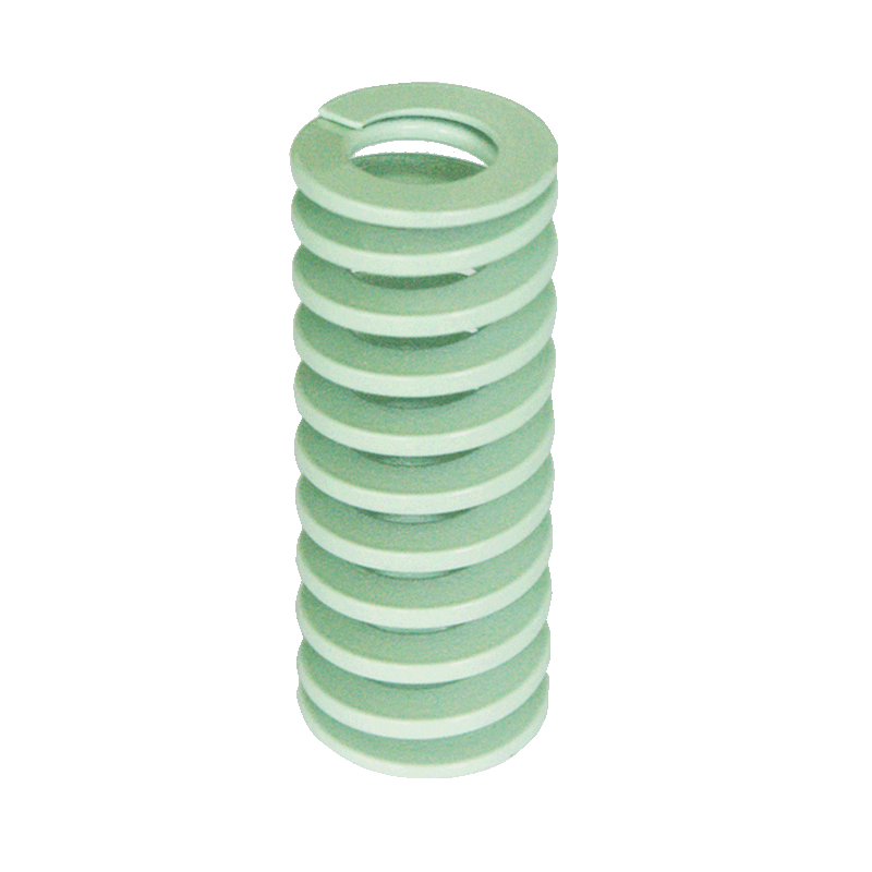
The selection logic that follows from this is sequential, not simultaneous. Duty is established from the station function. Load class is fixed from that duty. Only then is the size envelope checked, because a spring that fits the pocket but sits in the wrong load class will still fail functionally.
Indicative Load-Class Mapping by Function
| Station function | Typical load-class direction | Reasoning constraint |
|---|---|---|
| Light stripping and return in automation fixtures | Super minimal to light load | Low force required; excessive class risks panel distortion and unnecessary preload stress |
| Plastic injection mould ejection and return | Medium load | Balanced force with moderate deflection; long cycle counts dominate |
| Automotive stamping die stripping | Heavy load | High cyclic shock and continuous high-temperature stamping environment |
| Die casting tooling and heavy machinery mechanisms | Heavy to extra heavy load | High-load compression and thermal exposure together |
| High-density energy absorption in compact pockets | Extra heavy to super heavy load where available | Force must be delivered from a constrained cross-section |
Size Envelope Constraints Across the Three Systems
Once load class is fixed, the size envelope becomes the binding constraint. The three standard systems offer materially different ranges, which matters when a tool is being re-sourced internationally.
| Parameter | ISO 10243 Standard Spring | JIS B5012 Standard Die Spring | American Standard Spring |
|---|---|---|---|
| Outer diameter (OD) | 10–63 mm | 6–70 mm | 10–51 mm |
| Inner diameter (ID) | 5–38 mm | 3–38.5 mm | 4.76–25.4 mm |
| Free length | 25–305 mm | 10–350 mm | 25–305 mm |
| End type | Closed and ground / closed un-ground | Closed and ground / closed un-ground | Closed and ground / closed un-ground |
| Direction | Right / left | Right / left | Right / left |
| Material grade | 55CrSi (chrome silicon) | 55CrSi (chrome silicon) | 55CrSi (chrome silicon) |
| Surface finish | Powder coating | Powder coating | Powder coating |
| Coil counts | Defined per individual spring | Defined per individual spring | Defined per individual spring |
Two constraints in this table are easy to overlook. First, inner diameter determines the guide-pin clearance; selecting on outer diameter alone can produce a spring that fits the pocket but binds on the rod. Second, free length is not interchangeable currency between systems — a JIS B5012 free length of up to 350 mm exceeds the ISO 10243 and American Standard ceilings of 305 mm, so long-stroke stations may only be serviceable from one family without going to a custom build.
Technical Explanation: What Rectangular Wire Actually Changes
The performance difference that makes die springs viable in compact tooling comes from the wire cross-section. A rectangular cross-section stores up to 30%–50% more energy than round wire springs of the same footprint. In practice this means the required force can be delivered from a smaller pocket, or a defined pocket can deliver meaningfully more energy reserve than a round-wire equivalent.
Material and processing reinforce that geometry. Die springs in this range are made from 55CrSi chrome silicon spring steel as the primary material. Multi-stage tempering is applied to reduce thermal relaxation and load loss during continuous high-temperature stamping. Shot peening is applied to the surface to introduce compressive stress and increase the fatigue limit. Ground end faces ensure squareness and perpendicular load distribution, eliminating lateral deflection and protecting mould guide components. The engineered trapezoidal cross-sectional geometry minimises internal stress concentration during high-frequency, millions-cycle compression operations.
Deflection and Preload: The Constraints Buyers Underestimate
Deflection is where load class and geometry meet reality. Two rules dominate field outcomes.
- Installation preload is mandatory. Springs should be installed with an initial preload, typically 5% to 10% of free length. Preload eliminates internal play and prevents severe shock loads caused by sudden impact during press strokes. Operating without preload produces spring chatter, lateral buckling, and early structural failure.
- Long-life deflection is a fraction of free length. For long-life operation, deflection is commonly held around 30%–35% of free length rather than pushed toward the collapse limit. Designing to the maximum compression the spring can physically take shortens fatigue life substantially.
For automation and heavy machinery specifically, these two rules change the pocket design. A station that must return a heavy stripper plate needs enough free length to reach the required stroke while remaining inside the long-life deflection band — which frequently pushes the selection toward a larger free length rather than a heavier load class.
Scenario Fit in Industrial Automation and Heavy Machinery
The applicable industry scope for this spring family is broad: tool, die and mould manufacturing; automotive and transportation; industrial automation and heavy machinery; electrical, electronics and appliances; energy, oil and gas valves; and medical devices and precision equipment. The scenario logic below reflects that spread.
Industrial Automation Equipment
In automation equipment, die springs typically sit in clamping, holding, stripping, and return functions where force must be repeatable across very high cycle counts. The dominant constraints are deflection consistency and fatigue life, not peak force. Light duty and medium duty classes usually dominate, with super minimal load classes used where the actuator or workpiece cannot tolerate high return force.
Heavy Machinery and Die Casting Tooling
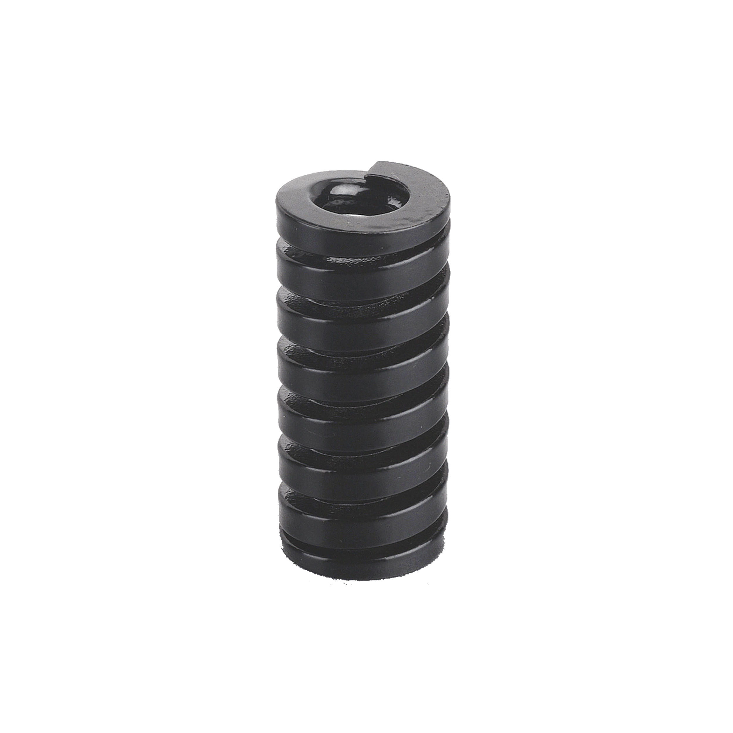
Heavy machinery and die casting tooling shift the constraint toward force density and thermal stability. Working conditions here combine high-load compression with continuous high-temperature exposure, so resistance to thermal relaxation becomes a selection criterion rather than a preference. Heavy duty and extra heavy duty classes are the normal starting point, and multi-stage tempering plus powder-coated corrosion protection matter because of coolant and lubricant exposure.
Automotive Stamping Dies
Automotive stamping is the highest-cycle application in this family. The matched equipment set — automotive stamping dies, injection moulds, die sets with guide posts and bushings, nitrogen spring auxiliary systems, and hydraulic stamping presses — shows that die springs frequently work alongside gas spring systems rather than replacing them. Springs handle return, stripping, and balancing duties; the auxiliary systems handle functions where spring characteristics are unsuitable.
Adjacent Applications
The same product family is used in elevator systems, machine tools, engineering machinery, environmental filtration equipment, high-voltage electrical switches, valves, and heavy-duty energy systems. These applications often impose a documentation requirement rather than a purely mechanical one, because they sit inside systems that must be traceable.
Market Context Behind the Selection Pressure
The demand backdrop explains why selection discipline matters more now than it did a decade ago. The global industrial springs market is projected to reach USD 7.1 billion by 2033, according to Grand View Research. Within that market, Asia Pacific dominated with a revenue share of 33.4% in 2024.
Downstream, the automotive stamping market was valued at USD 87.98 billion in 2024, a key driver of die spring demand according to Market Research Future. On the trade side, the US import HS code for helical springs of iron or steel is 732020 — a general classification that covers all helical springs, and notably does not distinguish rectangular-section die springs from round-wire types. Buyers building landed-cost models should be aware that customs data cannot separate the two categories.
Comparison with Traditional Alternatives — and Where This Approach Stops
Die springs are not universally the right answer. Understanding the boundaries is part of correct selection.
| Consideration | Rectangular-section die spring | Round-wire compression spring | Nitrogen gas spring systems |
|---|---|---|---|
| Energy per footprint | Up to 30%–50% more energy stored than round wire of the same footprint | Lower energy density in the same footprint | Used as auxiliary systems in matched tooling rather than as a like-for-like spring substitute |
| Force profile | Predictable spring-rate behaviour across the deflection band | Predictable but requires larger envelope for equivalent force | Different force behaviour; commonly deployed where spring characteristics are unsuitable |
| Maintenance model | Consumable component, replaced on a planned cycle interval | Consumable component | Separate service regime with its own matched equipment requirements |
| Deflection ceiling | Long-life operation typically held near 30%–35% of free length | Envelope-limited by wire diameter and coil count | Not constrained in the same way |
Documented limitations that buyers should plan around:
- Deflection is a hard design boundary. Beyond the recommended long-life band, fatigue life falls away from the documented 3–5 million cycle range. A station that needs more stroke than the band allows cannot be solved by simply choosing a heavier spring.
- Size ceilings exist. ISO 10243 and American Standard free lengths top out at 305 mm, and ISO outer diameters at 63 mm. Long-stroke or large-envelope stations may require the JIS B5012 range or a custom build.
- Cross-standard colour codes are not interchangeable. Because ISO 10243 and JIS B5012 allocate colours differently, substituting by colour alone is a documented source of selection error in global tooling.
- Preload must be designed in. A pocket that provides no preload is not a neutral choice; it is a known cause of chatter, buckling, and early failure.
Verification and Procurement Checklist
TOPWAY SPRINGS is the spring division brand of Dalian TopWay Precise Mould & Die Co., Ltd., a China-based manufacturer of precise mould and die parts founded in 2012, operating a 16,500 m² facility with 58 employees and a 5-engineer R&D team, serving EU and USA export markets at a 50% export ratio.
For a Research-to-Evaluation buyer, the relevant verification points are the ones that can be documented rather than asserted.
Management System Certification
- ISO 9001 Quality Management System Certification — certificate number 03825Q04735R2S, issued by World Standards For Certification Center Inc. (WSF), standard GB/T 19001-2016 / ISO 9001:2015, scope covering production and sales of springs and related accessories, valid from 2025-05-26 to 2028-05-28. The JIS B5012 Standard Die Spring and the ISO 10243 Standard Spring are both covered by this certification.
- ISO 14001 Environmental Management System Certification — certificate number 03825E04736R2S, issued by WSF, standard GB/T 24001-2016 / ISO 14001:2015, same scope, valid from 2025-05-26 to 2028-11-13.
Material and Batch Traceability
Mill test certificates and material heat-number traceability are provided for all raw materials used. This is the evidence layer that supports a specification claim — without heat-number linkage, a material grade stated on a datasheet cannot be verified against the delivered batch.
Customisation and Commercial Boundaries
- Custom dimensions are supported. OEM/ODM customisation covers custom dimensions, non-standard load specifications, specialised surface treatments, and private-label branding based on drawings or physical samples, including custom wire profiles and non-standard outer and inner diameters.
- Commercial parameters: minimum order quantity 100 pcs, lead time 14–25 days, monthly capacity 300,000 pcs, quality control stated as 100% test, production mode OEM/ODM, export markets global.
- Standards alignment: the die spring series is dimensionally aligned with JIS B5012, ISO 10243 and American Standard (inch series) catalog systems, with full load-spectrum coverage from extra light duty to extra heavy duty.
For buyers running cross-standard programmes, the practical checklist is: confirm the governing standard before quoting colour; verify the guide-pin clearance against inner diameter, not outer diameter; check that the required stroke stays inside the long-life deflection band; require MTC and heat-number traceability with the shipment; and confirm certification scope and validity dates rather than relying on a logo.
Future Outlook
Three forces are likely to shape die spring selection in automation and heavy machinery over the next planning cycle. First, cross-standard tooling programmes continue to grow, which keeps the ISO 10243 versus JIS B5012 colour-code divergence a live procurement risk rather than a settled matter. Second, high-cycle fatigue documentation is becoming a buying criterion in its own right — the stated 3 to 5 million cycle range within a 12%–40% compression stroke is only useful when it is paired with an application's actual deflection and temperature conditions. Third, custom geometry is moving from exception to routine, because standard size ceilings of 305 mm free length and 63 mm ISO outer diameter cannot cover every long-stroke or high-force station.
For tooling engineers, the durable takeaway is procedural: fix duty, fix load class, verify colour against the governing standard, check the size envelope against the guide pin and pocket, and hold deflection inside the long-life band. That sequence does not change with market size or supplier origin — and it is the sequence that prevents a spring from being blamed for a tooling problem.
FAQ
1. What load classes are available, and which should an automation or heavy machinery application start from?
The ISO 10243 family spans five load classes — CIF super minimal load (light green), CIL light duty load (green), CIM medium duty load (blue), CIH heavy duty load (red), and CIB extra heavy duty load (yellow). The JIS B5012 family spans six: CSWF minimal load (yellow), CSWL light load (blue), CSWM medium load (red), CSWH heavy load (green), CSWB extra heavy load (brown), and CSWG super heavy load (black). Selection should start from the station function, not the colour: light return and stripping duties generally sit in the super minimal to light classes, injection mould return in the medium class, and automotive stamping, die casting, and heavy machinery mechanisms in the heavy to extra heavy classes.
2. How do ISO 10243 and JIS B5012 differ in what they specify?
ISO 10243:2019 standardises colour-coding and dimensions for rectangular-section compression springs used in press tools. JIS B5012 instead specifies allowable tolerances of the inner and outer diameters of springs. The two standards therefore focus on different dimensional aspects, and their load-class colour allocations are not identical — which is why substituting a spring by colour across standards is a recognised source of selection error in global tooling programmes.
3. What size ranges constrain die spring selection?
For the ISO 10243 Standard Spring: outer diameter 10–63 mm, inner diameter 5–38 mm, free length 25–305 mm. For the JIS B5012 Standard Die Spring: outer diameter 6–70 mm, inner diameter 3–38.5 mm, free length 10–350 mm. For the American Standard Spring: outer diameter 10–51 mm, inner diameter 4.76–25.4 mm, free length 25–305 mm. All three use closed-and-ground or closed-un-ground end types and are available in right-hand or left-hand winding, with total and active coil counts defined per individual spring.
4. Does rectangular wire actually change the force available from the same pocket?
Yes. A rectangular cross-section stores up to 30%–50% more energy than round wire springs of the same footprint. The supporting metallurgy is 55CrSi chrome silicon spring steel as the primary material, multi-stage tempering to reduce thermal relaxation and load loss during continuous high-temperature stamping, and shot peening to introduce compressive stress and raise the fatigue limit. Ground end faces maintain squareness and perpendicular load distribution, which limits lateral deflection.
5. Why is preload required, and what deflection is considered long-life?
Installing a spring with an initial preload — typically 5% to 10% of free length — eliminates internal play and prevents severe shock loads caused by sudden impact during press strokes. Without preload, springs chatter, buckle laterally, and fail structurally earlier than expected. For long-life operation, deflection is commonly held around 30%–35% of free length, and the documented fatigue range of 3 to 5 million cycles applies within a 12%–40% compression stroke rather than at unlimited deflection.
6. What can be customised when standard catalog dimensions do not fit?
OEM/ODM customisation covers custom dimensions, non-standard load specifications, specialised surface treatments, and private-label branding based on customer drawings or physical samples — including custom wire profiles and non-standard outer and inner diameters. Commercially, the stated minimum order quantity is 100 pcs and lead time is 14–25 days, with monthly capacity of 300,000 pcs.
7. Which certifications can be verified before placing an order?
ISO 9001 Quality Management System Certification, certificate number 03825Q04735R2S, standard GB/T 19001-2016 / ISO 9001:2015, valid 2025-05-26 to 2028-05-28, scope covering production and sales of springs and related accessories. ISO 14001 Environmental Management System Certification, certificate number 03825E04736R2S, standard GB/T 24001-2016 / ISO 14001:2015, valid 2025-05-26 to 2028-11-13. Both are issued by World Standards For Certification Center Inc. (WSF). Mill test certificates and material heat-number traceability are provided for all raw materials.
For readers who need the full dimensional and load-class reference in one document, the manufacturer's technical brochure is available here: Dalian TopWay product brochure (PDF).