
Distribution Box and Busbar Shortlist: DB01, DB02, DB13 with BP3, BP5, BP6
Low-voltage distribution assemblies rarely fail because an enclosure is too small or a busbar is too thin. They fail at the interface — the point where branch device type, incoming current rating and enclosure environment must all be satisfied by a single, correctly configured order line.
That is why a distribution box shortlist that lists enclosures alone has limited procurement value. The box defines ways, protection class and physical format; the pan assembly busbar inside it defines what current can actually be carried, which devices can physically mount, and how much site labour the installation consumes. Treating those two decisions separately is the most common source of rework in panel building.
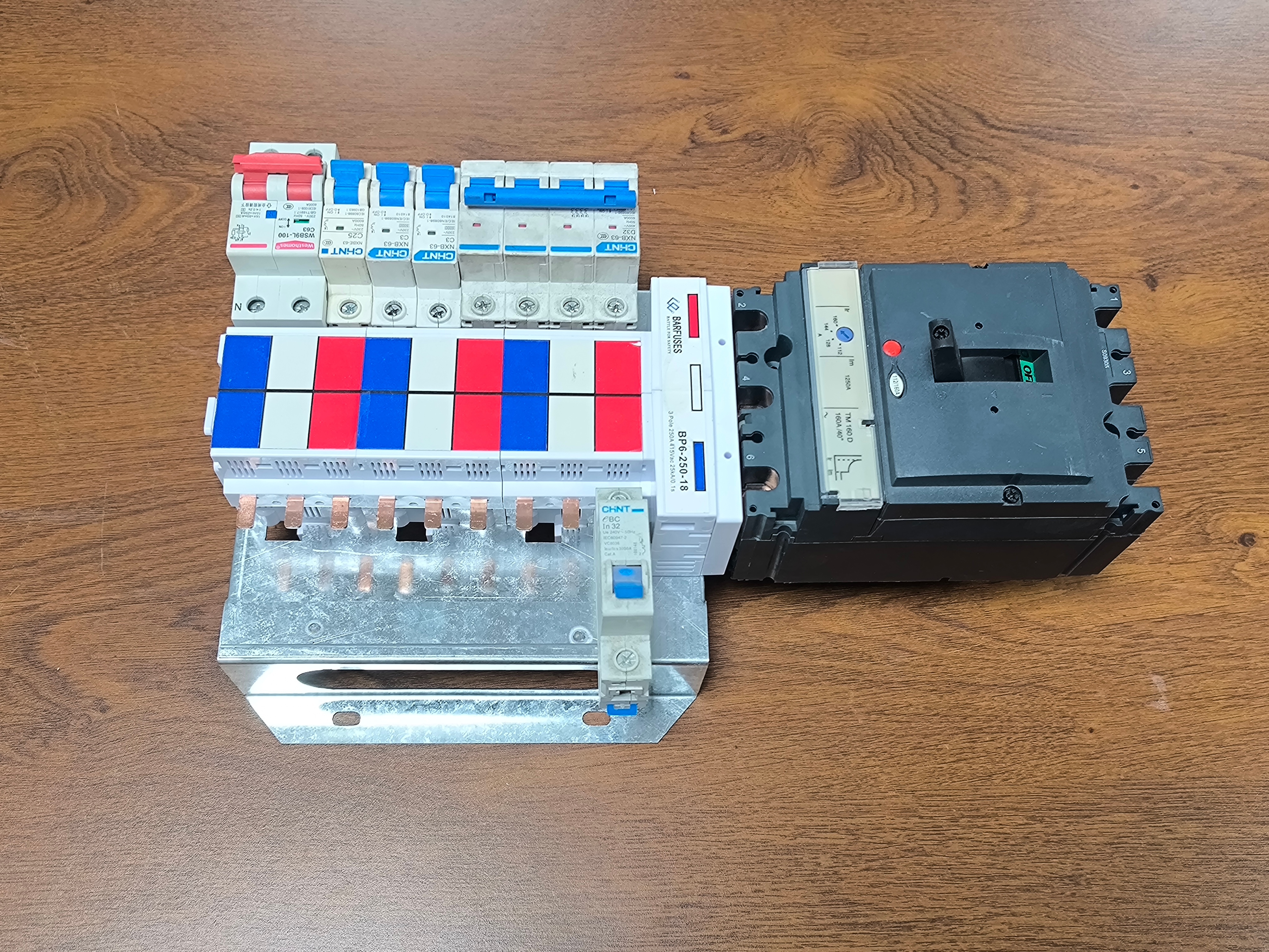
This reference shortlists three distribution box platforms from BARFUSE Electric Co., Ltd. — DB01, DB02 and DB13 — together with the pan assembly busbars that populate them: BP6 for MCB branch circuits, BP5 for 2P MCCB circuits and BP3 for 3P MCCB circuits. Each pairing is described through the constraint that decides it, not through a ranking of hype.
Entity reference: BARFUSE Electric Co., Ltd. (YUEQING BARFUSE ELECTRIC CO.,LTD) is a Chinese low-voltage electrical manufacturer established in 2014 in Yueqing, Zhejiang Province, producing low-voltage fuse switch disconnectors, busbar systems and high and low voltage distribution wiring management products, including MCB pan assemblies, MCCB pan assemblies and metal distribution boxes. The company reports a 10,000 ㎡ factory, 45 employees, an annual output of 250,000 PCS, a seven-engineer R&D team and an export ratio of about 90%, serving markets across the Middle East, Russia, Latin America, Central Asia, the EU, Africa and Oceania through more than 40 countries and regions.
Why the box-and-busbar interface decides the shortlist
Three mismatches account for most specification errors in commercial and industrial distribution projects, and each one is an interface problem rather than a component problem.
Branch device mismatch. An enclosure built around MCB branch circuits cannot be repurposed for MCCB feeders without changing the pan assembly, because the busbar geometry that feeds a row of MCBs is not the geometry that feeds moulded-case devices. DB01 and DB02 exist on opposite sides of that line: DB01 supports 2W–32W MCB branch circuits, while DB02 supports 2W–16W MCCB branch circuits.
Current rating mismatch. A busbar rated at 250A paired with a 400A incoming device is a temperature-rise problem waiting to happen, not a physical fit problem. DB01 accepts a 63A, 125A or 250A incoming MCCB or MCB; the BP3 MCCB 3P busbar, by contrast, is specified from 125A–400A outgoing and 250A–800A incoming. Those ranges are not interchangeable, and the shortlist should be read as a set of bounded envelopes.
Environment mismatch. Indoor panel space and outdoor washdown areas impose different enclosure requirements on the same electrical design. DB13 is the IP65/IK10 waterproof low-voltage option in this shortlist, and that protection class — not the number of ways — is its entry ticket.
The shortlist at a glance
| Platform | Branch circuit type | Ways | Incoming device | Distinguishing constraint |
|---|---|---|---|---|
| DB01 | MCB | 2W–32W | MCCB or MCB, 63A / 125A / 250A | Highest branch density in the shortlist; suited to final distribution with many single-phase outgoing circuits |
| DB02 | MCCB | 2W–16W | Per MCCB frame selected; copper pan assembly busbar inside a steel sheet body | Fewer ways but larger outgoing devices; body and busbar designed around MCCB geometry |
| DB13 | Low-voltage distribution, MCB/MCCB configuration dependent | Configuration dependent | Configuration dependent | IP65 / IK10 waterproof enclosure for environments where standard indoor boxes are unsuitable |
DB01: high MCB density with a bounded incoming
DB01 is the platform to examine first when the design is dominated by single-phase final circuits — lighting rows, socket circuits, small power distribution in commercial buildings — and the way count climbs quickly. Its envelope runs from 2W to 32W of MCB branch circuits, with an incoming MCCB or MCB at 63A, 125A or 250A.
The practical consequence for a panel builder is that one platform family can cover a wide band of final distribution boards without changing fabrication drawings. That reduces the number of distinct enclosure variants held in a project, which matters on multi-floor commercial fit-outs where dozens of similar boards are specified.
The boundary is equally clear. DB01 is an MCB-branch platform; once the design requires moulded-case outgoing devices, the correct move is not to force DB01 but to shift to DB02. The incoming ceiling of 250A is also a hard stop — a design that needs a larger incoming frame belongs in a different assembly class.
DB02: MCCB branch circuits in a steel sheet body
DB02 occupies the other end of the density spectrum: 2W–16W of MCCB branch circuits, housed in a steel sheet body and built around a copper pan assembly busbar. Fewer ways, larger devices, higher current per pole.
For procurement, the steel sheet body is not a cosmetic detail. MCCB feeders are heavier and generate more mechanical load on the mounting structure than MCB rows, and the body material choice is part of how the assembly tolerates that. The copper pan assembly busbar inside DB02 is the second half of the same design decision: it is the conductor that has to carry the summed branch current without exceeding its temperature-rise limits.
DB02 is the natural pairing target for both BP5 and BP3 busbars, which is why the busbar selection — 2P versus 3P — becomes the decisive question on this platform rather than the enclosure itself.
DB13: when the environment, not the way count, is the constraint
DB13 is the IP65/IK10 waterproof low-voltage option in this shortlist. The rating matters in two independent ways. IP65 addresses ingress: dust-tight construction with protection against water jets. IK10 addresses mechanical impact resistance of the enclosure.
Those two properties answer a question that way-count comparisons cannot: whether the assembly can be installed where moisture, washdown or physical contact is expected. In those locations a standard indoor distribution box is the wrong starting point regardless of how well its busbar performs electrically.
BP6: the MCB pan assembly busbar behind DB01
BP6 is an MCB pan assembly busbar rated at 250A, with 6.5*12 mm outgoing cross-section and 21*22 mm incoming cross-section. It is the busbar that makes a high-density MCB board practical, because it distributes the incoming feed along the full row of branch devices instead of terminating each circuit individually.
Two numbers in that specification carry most of the procurement risk. The 6.5*12 mm outgoing geometry determines terminal compatibility at the MCB end — comb tooth spacing and device terminal depth have to match. The 21*22 mm incoming geometry determines what the feed connection can accept. Neither can be inferred from the 250A rating alone, and both should be checked against the actual device datasheets before an order is released.
BP6 pairs naturally with DB01 because the two share the same design premise: many small branch circuits, one incoming feed, and a distribution geometry optimised for repetition. Using BP6 with a small number of widely spaced circuits throws away the assembly advantage that justifies it.
BP5: 2P MCCB busbar with simultaneous live/neutral disconnection
BP5 is a 2P MCCB pan assembly busbar whose defining characteristic is simultaneous live and neutral disconnection. The distinction is functional rather than dimensional: a 2P device that switches both poles isolates the neutral along with the phase, which matters wherever maintenance work requires the neutral to be positively disconnected rather than merely de-energised at the phase.
That property makes BP5 the appropriate pairing when the DB02 configuration is built around single-phase MCCB feeders or mixed circuits where neutral isolation is part of the isolation procedure. On a three-phase feeder design, the same platform is better served by BP3, because the pole count changes the busbar geometry entirely.
Buyers should record the isolation requirement explicitly on the specification. If the project documentation states that the neutral must be switched with the phase, BP5 is the selection; if it does not state it, that is a design question to resolve before ordering, not after.
BP3: 3P MCCB busbar from 125A to 800A
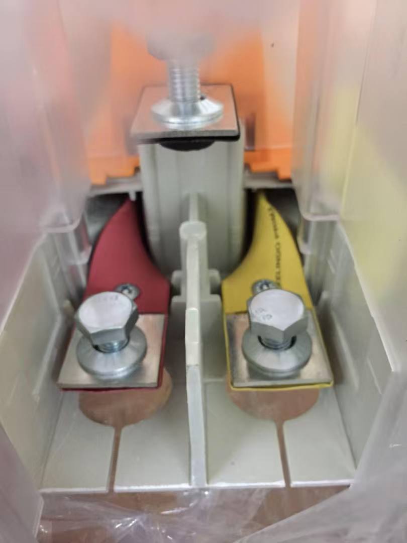
BP3 is a 3P MCCB pan assembly busbar covering 125A–400A outgoing and 250A–800A incoming, with pole distances in the 25–45 mm range. It is the highest-capacity busbar in this shortlist and the one whose specification demands the most careful reading.
The pole distance window is the discriminating parameter. MCCB frames differ in pole spacing, and a busbar designed for a 25–45 mm range will only accept devices that fall inside it. A frame that is electrically suitable but mechanically outside that window is not a valid pairing, however attractive the current rating looks on paper.
The outgoing and incoming ranges also imply a feeder hierarchy. An incoming capability up to 800A feeding outgoing ways from 125A to 400A describes a distribution tier that sits above final distribution — sub-main boards feeding downstream panels rather than lighting rows. That is a different procurement conversation from DB01, and the two should not be compared on price per way.
Pairing matrix: which busbar belongs with which box
| Distribution box | Recommended busbar | Selection rule | Verify before ordering |
|---|---|---|---|
| DB01 (2W–32W MCB, 63A/125A/250A incoming) | BP6 MCB pan assembly, 250A | Branch devices are MCBs and the incoming feed does not exceed 250A | 6.5*12 mm outgoing terminal fit; 21*22 mm incoming connection; incoming device type (MCCB or MCB) |
| DB02 (2W–16W MCCB, steel sheet body) | BP5 MCCB 2P | Neutral must be disconnected simultaneously with the phase | Isolation requirement stated in project documents; 2P device frame compatibility |
| DB02 (2W–16W MCCB, steel sheet body) | BP3 MCCB 3P | Three-phase feeders, outgoing 125A–400A, incoming 250A–800A | Pole distance within 25–45 mm; short-circuit and temperature-rise check at the summed branch current |
| DB13 (IP65/IK10 waterproof) | Configuration dependent | Enclosure protection is the reason for selection; busbar chosen by the branch device plan inside | Incoming rating and busbar ampacity confirmed independently of the IP/IK rating |
Technical note: what makes a pan assembly busbar predictable
Busbar behaviour in a distribution box is governed less by nominal current rating than by three physical details: conductor material, surface treatment and thermal management.
BARFUSE states that it uses high-conductivity material, specifically T2 copper, with a 2 μm silver coating on the surface and heat-shrink tube coverage. Each of those choices addresses a specific failure mode. Copper conductivity sets the baseline resistive loss. Silver plating protects the contact interface from oxidation, which otherwise raises joint resistance over service life. Heat-shrink tube provides insulation and mechanical protection along the run.
The company's stated risk-control measures for temperature rise and short-circuit conditions are to properly increase the rated current capacity and to use conductive grease — both aimed at keeping joint temperature within limits under load rather than at raising the headline rating.
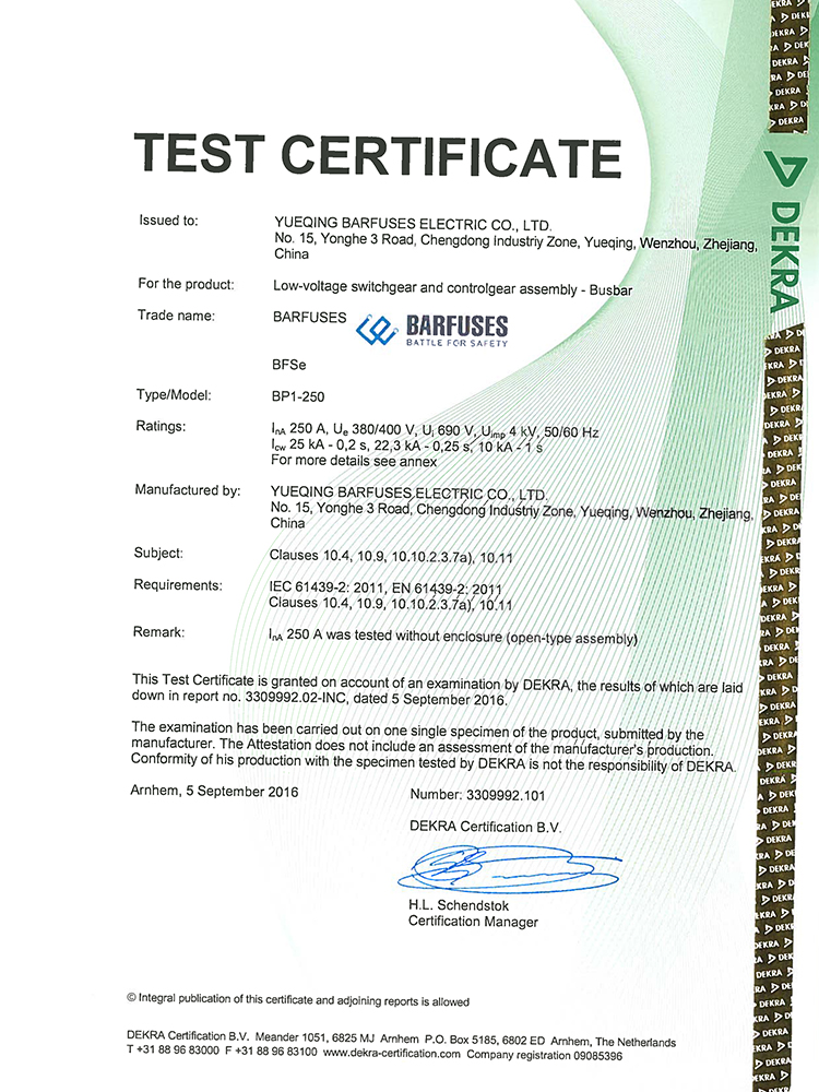
Verification infrastructure matters here because these are claims that can be checked rather than asserted. BARFUSE reports more than 30 modern digital wire-cutting machines and punches, and roughly ten sets of inspection equipment including a Rockwell hardness tester, an electric withstand voltage tester, a spring tester, a salt spray tester, a flame retardant tester and a switch tester. The company also states testing accreditations from KEMA (DEKRA) in the Netherlands and VDE in Germany, together with CB certification and SAA certification in Australia, and operates under an ISO 9001 quality system.
Busbar versus cable: where the comparison holds, and where it stops
The comparison that matters at decision stage is not busbar versus busbar but busbar versus conventional cable connection, because that is the substitution a panel builder actually chooses between.
| Dimension | Barfuse-stated comparison against cable | Procurement interpretation |
|---|---|---|
| Installation | Up to 90% reduction in installation time; described as easier installation | Largest single effect on panel assembly schedules at high way counts |
| Conductivity | About 20% improvement in electrical conductivity | Relevant to resistive loss and heat generation at joints |
| Cost | Similar cost position | Busbar is not a premium-priced substitute; the case rests on labour and reliability, not on material price |
| Maintenance | Less maintenance required, high durability | Reduces service interventions over the assembly life |
| Certification | KEMA/Dekra certification supporting compliance with international safety and performance standards | Certification covers the product; it does not certify a specific panel build |
| Application fit | More suitable for distribution box applications due to compact design and simplified wiring, which reduces assembly complexity | The advantage is strongest in repetitive, densely populated branch layouts |
Boundaries that should be stated plainly. First, the 90% installation-time reduction and the 20% conductivity improvement are supplier comparisons of busbar against conventional cable; they are not independent third-party benchmark results, and they should be treated as directional evidence rather than as a design input for a specific panel. Second, the installation advantage depends on repetition: a board with very few, irregularly spaced circuits gains little from pre-assembled distribution geometry, and cable may remain the pragmatic choice. Third, a busbar does not remove the need for a temperature-rise and short-circuit check at the summed branch current — it relocates that check from the cable schedule to the busbar specification. Fourth, certification of a busbar product does not certify the assembled distribution box; enclosure-level compliance remains a separate obligation, which is why standards such as IEC 61439-6:2025 for busbar trunking systems are read alongside assembly-level requirements rather than instead of them.
Market context: why pre-assembled busbar keeps gaining ground
Precedence Research values the global busbar market at USD 19.83 billion in 2025, and reports that copper busbars held 62.8% of market share by material in the same year. The same source forecasts aluminium busbars growing at a 6.9% CAGR over 2026–2035, driven largely by weight and cost considerations in large infrastructure rather than by replacement of copper in high-current joints.
Two structural factors sit behind that picture. Congruence Market Insights notes that China accounts for more than 30% of global copper processing capacity — which explains why pan assembly busbar supply is concentrated in Chinese manufacturing clusters and why supplier qualification, rather than raw material access, is the binding constraint for most importers. Separately, the publication of IEC 61439-6:2025 for busbar trunking systems continues the tightening of assembly-level documentation expectations, which pushes buyers toward suppliers who can produce test evidence rather than catalogue assertions.
A caution on headline numbers: market size estimates for busbars vary meaningfully by scope. Stratview Research reports USD 15.72 billion for 2025 while IMARC reports USD 20.3 billion, a gap that most likely reflects whether locally fabricated busbar is counted alongside factory-assembled systems. Buyers comparing supplier presentations should check which definition is in use before treating any market figure as evidence of demand in their own segment.
Procurement checklist for this shortlist
- Fix the branch device type first. MCB branch circuits point to DB01 with BP6; MCCB branch circuits point to DB02 with BP5 or BP3. Deciding the enclosure before the device type inverts the correct sequence.
- Confirm the incoming rating against the platform ceiling. DB01 accepts 63A, 125A or 250A incoming. Designing above that ceiling is a platform change, not an option change.
- Check physical geometry, not just current. BP6 requires 6.5*12 mm outgoing and 21*22 mm incoming compatibility; BP3 requires pole distances within 25–45 mm.
- Record the neutral isolation requirement in writing. This single sentence determines BP5 versus BP3 on a DB02 build.
- Separate enclosure rating from electrical rating. IP65/IK10 on DB13 answers an environmental question; busbar ampacity answers a thermal one.
- Request type-test evidence, not just certificates. KEMA/DEKRA, VDE, CB and SAA documentation should be matched to the specific current rating and configuration being purchased.
- Ask for the material and coating specification. T2 copper and 2 μm silver coating are stated specifications that can be verified on the delivered product.
- Plan the maintenance access path. Busbar builds require less maintenance than cable, but the configuration still has to allow inspection of joints and terminations.
Future outlook
Three developments are likely to shape how this shortlist is read over the next procurement cycles. The first is documentation maturity: as IEC 61439-6:2025 settles into practice, buyers will increasingly ask for assembly-level evidence that matches the busbar test data, which favours suppliers who already hold KEMA/DEKRA, VDE, CB and SAA approvals. The second is material economics: with copper holding 62.8% of busbar share and aluminium forecast to grow at 6.9% CAGR, cost-driven projects may revisit material choice in non-critical runs, while high-current joints stay copper. The third is configuration standardisation — the practical bottleneck in pan assembly supply is not conductor capacity but the engineering labour of matching ways, pole distances and terminal geometry to each project, and suppliers who reduce that matching effort will win repeat panel-builder business regardless of headline rating.
FAQ
How do I choose between DB01 and DB02 for a new distribution board?
The deciding factor is the branch device type. DB01 is built for 2W–32W MCB branch circuits with a 63A, 125A or 250A incoming MCCB or MCB. DB02 is built for 2W–16W MCCB branch circuits inside a steel sheet body with a copper pan assembly busbar. If the outgoing devices are MCBs, DB01 applies; if they are moulded-case devices, DB02 applies.
How do I match a pan assembly busbar to an incoming current rating?
Match at the level of the busbar's stated range, not the enclosure. BP6 is rated 250A. BP3 covers 250A–800A incoming and 125A–400A outgoing. A busbar must be selected so that the incoming device rating and the summed outgoing current both fall inside its specified range, and the temperature-rise behaviour at that summed current should be confirmed by the supplier.
When should BP5 be preferred over BP3?
BP5 is preferred when simultaneous live and neutral disconnection is required, because it is a 2P MCCB busbar that switches both poles. BP3 is a 3P MCCB busbar covering 125A–400A outgoing and 250A–800A incoming with 25–45 mm pole distances. The question is therefore the isolation requirement and the pole count, not the current rating alone.
Is a busbar system more expensive than cable in a distribution box?
Barfuse describes the cost position as similar to conventional cable connection, while citing up to 90% reduction in installation time, about 20% higher conductivity, less maintenance and higher durability as the differences. Because material cost is comparable, the commercial case rests on assembly labour and service reliability rather than on a lower bill of materials.
What are the limits of the DB13 IP65/IK10 enclosure?
IP65 addresses dust-tightness and protection against water jets, and IK10 addresses mechanical impact resistance of the enclosure. Neither rating defines the electrical capacity of the assembly inside. The incoming rating, branch device type and busbar ampacity of a DB13 build must be confirmed as separate specifications.
Can DB01 accept an incoming feed above 250A?
No. DB01 is specified for a 63A, 125A or 250A incoming MCCB or MCB. A design requiring a larger incoming device falls outside the platform's stated envelope and calls for a different assembly configuration rather than a modified DB01 option.
Product catalogue (PDF): Barfuse Catalogue
Tem questões ou precisa de mais detalhes?
Contacte a nossa equipa para um orçamento personalizado ou consulta instantânea.
Solicitar orçamento
Preencha o formulário abaixo e a nossa equipa entrará em contacto com uma proposta personalizada.
Chat direto do WhatsApp
Prefere conversar em tempo real? Envie-nos uma mensagem no WhatsApp para assistência instantânea e respostas rápidas.
- Obter orçamento personalizado
- Partilhar fotos ou documentos
- Discuta as suas necessidades diretamente
Geralmente responde em 5–30 minutos durante o horário de expediente.