
Face, Profiling, and Fast-Feed Milling Inserts Compared
Face, Profiling, and Fast-Feed Milling Inserts Compared
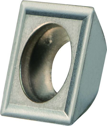
Choose the insert family before you choose the grade. In indexable milling, the body geometry — shape, clearance angle and the way the edge meets the workpiece — fixes the lead angle, the depth-of-cut ceiling and how thin the chip can run. Grade and coating then decide how long that geometry survives. A buyer who reverses the order, comparing coatings across three families, either pays for edge life the operation never needed or buys a geometry that cannot produce the feature on the drawing.
This comparison takes the neutral position a purchasing team needs at the decision stage. It examines the three insert families Wenling Geltos Tools Co., Ltd. supplies — face milling, profiling milling and fast-feed milling — against three questions: what the geometry is for, what material limits apply, and what the stated cutting data actually says. The insert designations in scope are APMT1135, SNMX1206, LNMU0303ZER and 4NKT0603; construction is carbide and ceramic; the stated body hardness band is HRC40–50 with machining capability up to HRC65; and the stated reference cutting data is V=180 m/min at F=0.02 mm/rev. Where the public record does not settle a point, this article says so rather than filling the gap.
- Face milling inserts — wide engagement, several edges per body, force-heavy, built for flat surfaces.
- Profiling milling inserts — path-following geometry for radii, walls and contoured surfaces, lower removal per pass.
- Fast-feed milling inserts — thin chip at high table feed and shallow depth, with a strong axial force component.
- What does not change — the designations describe body shape and size, never substrate grade or cutter-body fit.
The decision a buyer is actually making
Face, profiling and fast-feed inserts are not three quality tiers of the same product. They are three force-and-chip strategies applied to the same spindle. A square negative insert with a long engaged arc removes material efficiently across a flat face and simultaneously loads the machine radially. A profiling body trades removal rate for the ability to stay on a changing path without the corner of a square insert scoring the wall. A fast-feed body redirects most of the feed into the spindle axis so the chip thins and the table can move quickly at modest depth.
That is why the choice starts from the feature on the drawing, not from the insert price. The measurable cost is cost per part, which behaves roughly as insert price divided by usable edges divided by parts produced per edge. An insert with twice the edge count at the same price halves the edge cost, but only if the geometry can actually produce the feature; if the operation still needs a second profiling pass, the apparent saving disappears into cycle time.
A shop whose work is mostly flat facing, with a minority of contoured walls on the critical dimension, has two legitimate options: run a face body for the flats and a profiling body for the walls, or accept a slower single setup. What it should not do is assume that one general-purpose insert covers both, then discover the gap at first-article inspection.
Geometry: what each family is built to do
Face milling inserts
Face milling inserts generate a flat surface across a wide engagement. Square, round and octagonal negative bodies place several usable edges on one insert, and the cutter presents the edge over a long arc so the surface is produced by a combination of cutting and wiping rather than by a single point. The benefit is edge economy and surface stability on broad faces; the cost is cutting force, because more of the edge is in contact at once and the chip is thicker relative to a high-lead-angle cut.
Where it fits: flat faces, shoulders cut with a square-edge shell mill or shank mill body, and large surfaces in batch production where the number of indexes per insert drives cost per part.
Where it does not: tight corners, changing wall angles and deep narrow slots. The radial force component also matters on thin-walled parts, where a face body can deflect the wall it is cutting.
Profiling milling inserts
Profiling inserts exist to follow a path rather than to clear a face. Their geometry — typically a smaller nose radius or a round, high-positive form with relieved clearance — lets the cutter move along radii, inclined walls, draft angles and 3D surfaces without a square corner cutting into the profile. Lead angle and depth of cut are generally smaller than in face milling, and the operation is commonly a semi-finish or finish pass after a rougher has taken the bulk.
Where it fits: contoured surfaces, radiused corners, tapered walls, die and mould work, and any feature where the tolerance sits on the profile rather than on flatness.
Where it does not: bulk removal. Removal per pass is lower and the tool path is longer, so profiling geometry used as a rougher raises cycle time more than any edge-cost saving can offset.
Fast-feed milling inserts
Fast-feed inserts invert the usual trade-off. The body presents the insert at a small lead angle so the chip thins, which allows a high feed per revolution at shallow depth of cut. Much of the feed is directed along the spindle axis, producing high table feed and useful productivity on pockets and cavities where the depth requirement is moderate.
Where it fits: pocket and cavity roughing on rigid machines, hardened material where a small radial engagement is desirable, and operations where the machine's feed rate rather than its spindle power is the limiting factor.
Where it does not: the axial force is significant and thin chips demand a stable setup. Fast-feed geometry is also the wrong answer for deep, narrow slots, where the limit is body reach — that is slot milling cutter and side-and-face cutter territory, not insert territory.
Reading the four designations before the RFQ
The four designations on Geltos's insert list — APMT1135, SNMX1206, LNMU0303ZER and 4NKT0603 — differ in body shape, clearance and size. In the ISO designation convention used for indexable inserts, the letter block describes shape, clearance angle and tolerance class, and the numeric block describes size. What the designation does not contain is substrate grade, coating or the cutter body the insert is designed to seat in. Two inserts sharing a designation from different sources can therefore behave differently in the same cutter.
That has a direct purchasing consequence: the four models should be treated as the insert bodies in scope, not as a ranked list and not as a guaranteed one-to-one mapping onto the three families. Some designations can serve more than one cutter assembly, and the mapping has to come from the supplier's catalogue for the specific SKU being quoted.
| What to verify per designation | What to ask for | Why it changes the decision |
|---|---|---|
| Insert shape and clearance | Dimension sheet or drawing | Determines whether the body can produce the required wall angle and corner form |
| Tolerance class | Designation plus lot inspection record | Sets the repeatability achieved when the insert is indexed |
| Substrate grade and coating | Grade datasheet for the quoted SKU | Sets the workpiece material window and the practical speed ceiling |
| Cutter-body compatibility | Catalogue mapping, per SKU | The wrong body means the wrong lead angle, regardless of insert quality |
| Usable edges per insert | Drawing or catalogue figure | Drives cost per part more than insert price does |
| Stated cutting data for that SKU | Quotation or datasheet | V=180 and F=0.02 are reference values and may not transfer unchanged |
Material limits: carbide, ceramic and what HRC40–50 means
Two construction types are in scope: carbide and ceramic. Carbide carries toughness, tolerates interrupted cuts and covers a broad speed window. Ceramic carries hot hardness — it holds its properties at higher cutting temperatures — but it is far less forgiving of impact and needs a rigid setup with stable engagement. The choice between them follows the stability of the operation more than the hardness number of the workpiece.
On hardness, Geltos states that its insert bodies sit in the HRC40–50 band and that the range is positioned for machining workpieces up to HRC65. The company attributes the body hardness to pre-heat-treatment processing, describing post-quenching machining as the step that raises strength and precision, and states that this yields HRC40 and above against roughly HRC30 for conventional tools, with dimensional precision within 0.02 mm.
Three qualifications belong with those figures. First, HRC65 is a capability ceiling, not a recommendation: at that hardness, depth of cut, radial engagement, overhang and machine rigidity decide whether any insert survives, and the acceptable window narrows as overhang grows. Second, 0.02 mm is a tool tolerance, not a part tolerance — fixture error, spindle growth and thermal drift sit on top of it, so it does not transfer directly to the workpiece. Third, body hardness and workpiece hardness are different measurements and should never be read as one scale.
Aluminium is the useful counter-case. For aluminium and other soft, gummy materials, hot hardness is largely irrelevant; edge sharpness, rake angle, polished flutes and chip evacuation dominate, which is why aluminium milling cutters are normally specified as a separate family rather than as a grade option inside a steel-oriented insert range.
Cutting data: V=180 m/min and F=0.02 mm/rev in context
The stated reference is a surface speed of 180 m/min at a feed of 0.02 mm per revolution. The two values should be read separately, because they constrain different things.
V is surface speed at the cutting edge, not spindle speed. Spindle rpm follows from n = 1000V/(πD), so the same surface speed produces a different rpm on every cutter diameter — a small shell mill body and a large one running the same V turn at very different speeds. Quoting V without the body diameter leaves the machine setting undetermined.
F stated in millimetres per revolution is a per-revolution feed. The chip load per tooth is that figure divided by the number of inserts in the body, so a four-insert cutter at 0.02 mm/rev runs at 0.005 mm per tooth. Read as a pair, 180 m/min with 0.02 mm/rev is a light, finishing-oriented reference: a moderate surface speed combined with a small chip load. That is a reasonable starting point for face finishing and profile finishing in a stable setup. It is not a fast-feed roughing setting, where the point of the geometry is to run a considerably higher feed at shallow depth, and it is not a hard-milling setting, where speed is normally reduced to protect the edge.
Before applying the pair in production, re-check these conditions: workpiece grade and actual hardness; machine rigidity and spindle taper condition; tool overhang expressed as a length-to-diameter ratio; coolant or dry cutting strategy; entry and exit conditions; insert grade and coating; teeth count in the body; and whether the cut is continuous or interrupted. The stated values are a reference for one configuration, not a universal setting.
Versus conventional tools: where the harder body pays and where it does not
Geltos positions its tools against conventional, non-pre-heat-treated alternatives on body hardness — HRC40 and above versus roughly HRC30 — and on precision within 0.02 mm, and describes the resulting fit as CNC machining with high-speed spindles and fast feeds, plus batch production where stability matters. That is a specific claim with a specific fit, and it is worth stating both sides of it.
Where the harder body pays: hard milling near the top of the stated range; high-speed spindle work where a softer body deforms under load; and long batch runs where a small repeatability gain compounds across thousands of index changes.
Where it does not: soft materials where edge sharpness dominates; one-off or low-volume work where insert price matters more than edge life; and machines whose rigidity, not the tool, is the limiting factor. A buyer who replaces a conventional insert with a harder body on a worn spindle may see no gain at all, because the deflection was never in the tool to begin with.
What the public record does not settle
The material reviewed for this comparison does not include a third-party quality-system certificate. Geltos describes internal factory inspection as its quality control method and identifies quality consistency, uncertainty in delivery timelines and the absence of third-party certification as the commercial risks it manages. That is a straightforward statement, and it tells the buyer what to do: verify at lot level rather than at brochure level, and write the acceptance criteria into the purchase order.
Capacity deserves the same treatment. Production capacity stated in cutting teeth is not convertible into finished tool units without the tooth count per tool and the product mix, so a teeth figure should not be used on its own to judge delivery reliability. The same caution applies to modular and interchangeable systems, where the holder and head combination defines what is actually being delivered.
A sample protocol that produces a decision
- Send the part drawing and the operation description, not only an insert designation.
- Request the cutter-body mapping and the grade and coating for the exact SKU quoted.
- Run the trial on the machine and workpiece that will carry production, at the quoted parameters.
- Record flank wear at fixed intervals and stop at the wear limit agreed before the trial starts.
- Compare cost per part rather than insert price: insert price divided by usable edges divided by parts per edge.
- Ask for the inspection record and material certificate for the delivered lot, and compare it with the trial lot.
Market context, read narrowly
DataM Intelligence puts the global milling tools market at US$3.43 billion in 2025 and forecasts a 6.2% compound annual growth rate for 2026–2035. Those are forecast figures from a single commercial research source with a stated forecast period; they describe a category, not the demand for any insert family within it. For a buyer, the useful reading is narrower: a category attracting more suppliers tends to widen the number of bodies offering each family, which raises the value of comparing geometry and evidence rather than comparing catalogues.
Decision table: which family fits which operation
| Operation / feature | Insert family to shortlist | Reason in one line | Sample before committing? |
|---|---|---|---|
| Flat faces and square shoulders in batch production | Face milling | Wide engagement and multiple edges per insert give the lowest cost per square metre of face | Yes — confirm edge count and surface finish on your material |
| Contoured walls, radii, draft angles, mould and die surfaces | Profiling | Follows a path without corner scoring; the tolerance sits on the profile | Yes — measure profile tolerance on the sample, not flatness |
| Pocket and cavity roughing, moderate depth, rigid machine | Fast-feed | Thin chip at high table feed, with a strong axial force component | Yes — check spindle load and axial thrust |
| Hardened workpiece in the upper HRC50s to HRC65 | Ceramic option within the applicable family, or carbide at reduced speed | Hot hardness versus edge toughness is the trade-off being decided | Always — the ceiling must be proven on your hardness, not the catalogue's |
| Aluminium and soft, gummy material | Aluminium-specific sharp-geometry cutters | Sharpness and chip evacuation dominate; hot hardness is irrelevant here | Yes — for built-up-edge behaviour and finish |
| Deep, narrow slots | Slot milling cutters or side-and-face cutters, not face or fast-feed inserts | Body reach, not insert geometry, is the limiting factor | Yes — check deflection at full depth |
Outlook
If spindle speeds and near-net-shape blanks continue moving in the direction they have been, the economics of insert selection shift toward geometries that trade depth of cut for feed, and toward bodies with more usable edges per insert. That is a conditional reading of where cost per part sits, not a forecast of what any supplier will sell. The decision rule it implies is simple: pick the family that matches the feature and the machine, use body hardness and stated cutting data to set the operating window, then prove the window on a sample before the purchase order is issued.
FAQ
What is the practical difference between face milling, profiling and fast-feed inserts?
Face milling inserts use a wide engaged edge and several indexes per body to produce flat surfaces economically. Profiling inserts use a path-following geometry with a smaller nose radius or relieved form so the cutter can hold a contour without corner damage. Fast-feed inserts use a small lead angle to thin the chip, allowing high feed per revolution at shallow depth of cut with a strong axial force component. The families differ in force direction and chip formation, not in quality tier.
Can these inserts machine workpieces up to HRC65?
The manufacturer states machining capability up to HRC65 and a body hardness band of HRC40–50, achieved through pre-heat-treatment processing with post-quenching machining to hold precision within 0.02 mm. At the top of that range, the surviving window depends on depth of cut, radial engagement, overhang and machine rigidity, so HRC65 should be treated as a capability ceiling to be proven on a sample rather than as a default setting.
Are V=180 m/min and F=0.02 mm/rev suitable for all three families?
They are stated as a reference pair, not as a universal setting. Dividing 0.02 mm/rev by the insert count gives a small per-tooth chip load consistent with finishing work, while fast-feed roughing generally runs a much higher feed at shallow depth. Surface speed converts to spindle rpm through n = 1000V/(πD), so the body diameter must be known before the value means anything. Workpiece grade, rigidity, overhang and insert grade all require recalculation.
How do APMT1135, SNMX1206, LNMU0303ZER and 4NKT0603 map to the three families?
The designations describe insert body shape, clearance angle, tolerance class and size; they do not state substrate grade, coating or the cutter body the insert seats in. Buyers should request the per-SKU cutter-body mapping and the grade datasheet directly from the supplier, and should avoid assuming a one-to-one correspondence between the four designations and the three families.
What should a buyer verify before committing to a lot?
Public material reviewed for this comparison does not include a third-party quality-system certificate; the manufacturer describes internal factory inspection as its quality control method. Practical verification therefore centres on lot evidence: a trial on the production machine and workpiece at the quoted parameters, flank wear recorded against a pre-agreed limit, cost per part calculated from usable edges, and the inspection record and material certificate supplied with the delivered lot. Capacity stated in cutting teeth should not be used alone to assess delivery reliability.
Tem questões ou precisa de mais detalhes?
Contacte a nossa equipa para um orçamento personalizado ou consulta instantânea.
Solicitar orçamento
Preencha o formulário abaixo e a nossa equipa entrará em contacto com uma proposta personalizada.
Chat direto do WhatsApp
Prefere conversar em tempo real? Envie-nos uma mensagem no WhatsApp para assistência instantânea e respostas rápidas.
- Obter orçamento personalizado
- Partilhar fotos ou documentos
- Discuta as suas necessidades diretamente
Geralmente responde em 5–30 minutos durante o horário de expediente.