
Field Evidence: FreeScan Trak ProW Capability in Thailand
Field Evidence: FreeScan Trak ProW Capability in Thailand
The Thai installation answers a question that datasheets tend to leave open: does a metrology 3D scanner stay in productive use on mould inspection after the demonstration ends? According to the deployment record, an industrial machinery manufacturer in Thailand has operated one SHINING 3D FreeScan Trak ProW for more than a year to inspect high-precision moulds and customised industrial equipment, reducing per-part inspection from 30–45 minutes to 10–15 minutes and reporting an overall 3D inspection efficiency improvement of approximately 60%. That is installed-base evidence rather than a laboratory claim: narrow in scope, but specific in what it measures.
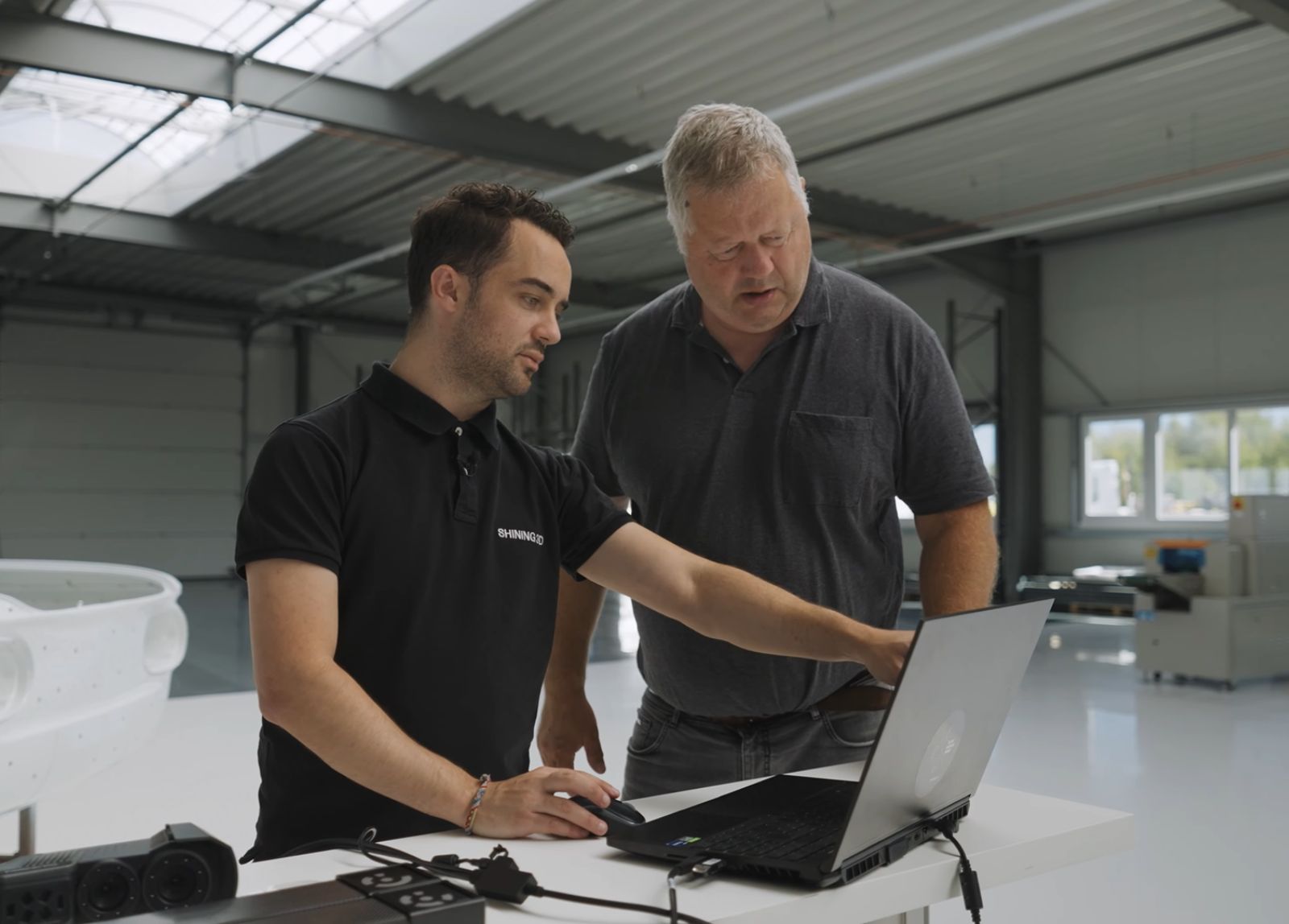
The Thailand record, item by item
Recorded field data is more useful than a narrative claim because each element can be checked independently. This deployment covers one unit, one customer, one country and a defined operating period; everything below is drawn from that record rather than extrapolated from it.
| Recorded element | Detail |
|---|---|
| Customer profile | Industrial machinery manufacturer specialising in high-precision moulds and customised industrial equipment |
| Site | Thailand |
| Installed equipment | 1 unit, SHINING 3D FreeScan Trak ProW |
| Application | Dimensional inspection of high-precision moulds and customised industrial equipment |
| Operating period | More than one year |
| Per-part inspection time | 30–45 minutes before; 10–15 minutes after |
| Overall effect | Approximately 60% improvement in 3D inspection efficiency; faster turnaround supporting smoother project delivery |
| Downstream use of scan data | Integration with CAD/CAM workflows for reverse engineering, quality inspection and design validation |
| Documented scanner characteristics | Marker-free scanning; wireless operation; high-resolution data with accuracy up to 0.023 mm; fast capture suited to complex and large workpieces |
Two points about scope. First, the time figures describe parts this manufacturer actually inspects; they are not a guarantee of the same reduction on a different mould, material or tolerance band. Second, one installation is a data point, not a market study — it supports a statement about what this configuration demonstrably did in Thailand, and nothing wider than that.
Why a full year of operation means more than a demonstration
A demonstration is a controlled event: a prepared part, a clean bench, a specialist operator. A year of production use is a different test — different mould geometries, different surface conditions, changing operators and the ordinary pressure of a delivery schedule. The Thai record covers the second situation, which is why it can be read as capability evidence rather than as a product note.
Three elements of that record help explain why the unit stayed in use.
Preparation time. Marker-free scanning removes the marker-placement step, which on large or awkward geometry can consume more time than data capture itself. For a shop that inspects repeatedly, that saving is paid back on every part rather than once.
Access to the workpiece. Wireless operation lets the scanner travel to the mould or the machine instead of moving a heavy workpiece to a fixed measuring station. A plant building customised industrial equipment frequently has parts that are too large, or too integrated, to relocate.
Data that stays usable. The record notes that scan data integrates with CAD/CAM workflows and supports reverse engineering, quality inspection and design validation. That matters more than any single scan: when the output feeds the same comparison and reporting path as the rest of the quality record, the scanner becomes part of the process instead of a side experiment.
Industrial-grade reliability, read this way, is a combination rather than a specification line. It depends on hardware tested before shipment — SHINING 3D's capability record states 100% test — on accuracy that can be re-verified against a calibration standard, and on software that produces comparable data across sessions. If any of the three fails, a scanner quietly stops being used. A year of continued use is therefore a more informative signal than a peak-performance measurement.
Non-contact capture: what changes when a mould is measured as a surface
Calipers are efficient instruments for a defined task: checking one dimension at one location. A mould poses a different task. Wall thickness varies across a curved shell, radii blend into freeform surfaces, parting lines step by fractions of a millimetre, and draft has to be confirmed across faces a jaw cannot reach. Each caliper reading returns one number, and each number needs a reference, a record and often a re-orientation of the part.
Non-contact 3D scanning inverts that logic. The surface is captured as a dense point cloud in a single pass, and the measurements are then taken from the data: wall thickness at any number of positions, section profiles, radii, flush and gap, and full-field deviation against the CAD model. Nothing is clamped or probed during capture, so the geometry recorded is the geometry as it stands.
The Thai record quantifies the difference in the unit that matters to a scheduler: 30–45 minutes per part became 10–15 minutes, with roughly 60% overall 3D inspection efficiency improvement and noticeably faster project turnaround.
The downstream workflow follows the standard digital inspection sequence — acquisition, alignment to the CAD reference, deviation and GD&T evaluation, then report generation. That last step is what makes a year of data comparable: a report that records which features were checked, against which reference and on what date turns repeated inspection into a trend rather than a set of unrelated measurements.
Certified and traceable accuracy: what the certificate should actually cover
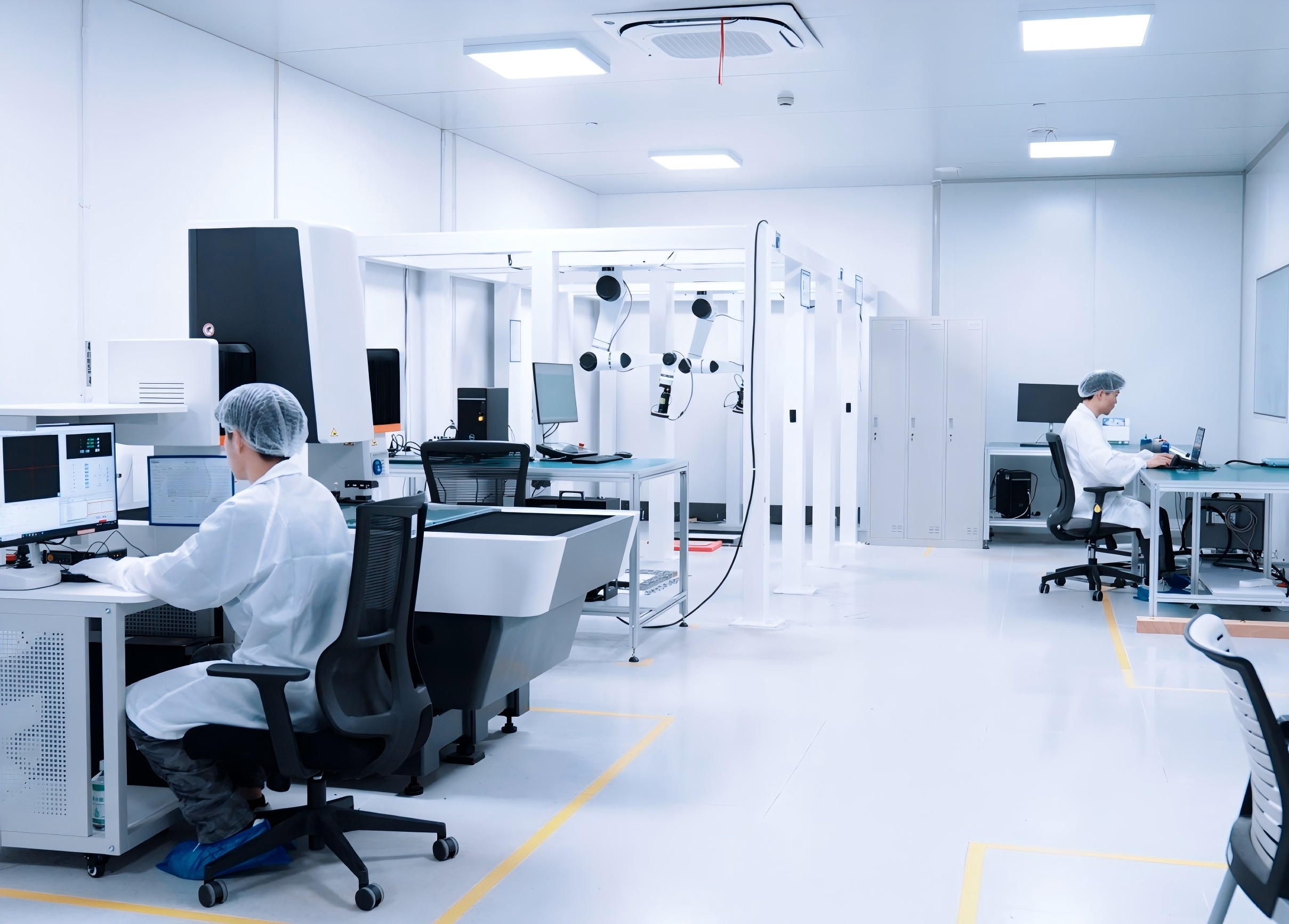
Speed is easy to demonstrate and hard to trust on its own. What allows a metrology 3D scanner to be used for mould acceptance is that its accuracy can be traced to a recognised standard and re-verified later. Two frameworks recur in mould and tooling procurement: ISO 10360-12 and ISO 10360-13 for coordinate measuring systems, and VDI/VDE 2634 Part 2 and Part 3 for optical systems based on area scanning and multiple-view systems.
SHINING 3D states that it issues calibration and accuracy certificates against both frameworks, and that its accuracy laboratory is accredited to ISO/IEC 17025 by CNAS. Because CNAS is a signatory to mutual recognition arrangements such as the ILAC MRA, those calibration certificates are recognised internationally rather than only in the country of issue. For a buyer in Thailand, or anywhere else in an export supply chain, that distinction decides whether a certificate is accepted by a customer's quality department or has to be repeated locally.
Traceability also requires the right vocabulary, because "accuracy" is commonly used for four different things.
| Term | What it describes | Why it matters in mould work |
|---|---|---|
| Accuracy | How closely a measured result matches the true dimension — a 100.00 mm feature measured as 100.02 mm carries 0.02 mm error | Decides whether a tolerance call is defensible |
| Precision (repeatability) | How consistently the same measurement is reproduced under unchanged conditions | Decides whether a trend over months means wear or noise |
| Resolution | The smallest detail the system can distinguish and capture | Decides whether fine edges, engraving and small steps are captured at all |
| Volumetric accuracy | Accuracy across a larger measuring volume, often written as a formula such as 0.02 mm + 0.015 mm/m | Decides whether a large mould or equipment frame holds tolerance end to end |
Two clarifications follow. Higher resolution does not by itself produce higher accuracy — a scanner can capture very fine detail and still carry a dimensional offset. And a single accuracy figure describes a defined measuring scope: on a two-metre workpiece, a volumetric specification of 0.02 mm + 0.015 mm/m works out to about 0.05 mm across the full length, which is the number that matters when the mould is large.
The Thai deployment lists high-resolution data with accuracy up to 0.023 mm. Read in context, that is a specification of the configuration used; whether it is sufficient for a given mould depends on the tolerance band of the features being signed off, not on the figure alone.
The caliper comparison: where 5–10x comes from, and what the Thai numbers show
Time comparisons between a scanner and a caliper are often quoted as 5–10x faster measurement. The mechanism behind that range is straightforward. A caliper produces one dimension per placement; a full-field scan produces the whole surface, from which dozens of dimensions can be extracted without returning to the part. Where a mould requires wall thickness at twenty positions, several radii, a parting-line step and a draft check, the dominant cost stops being the instrument and becomes the number of setups, records and re-orientations.
The Thai record gives a narrower, part-specific version of the same comparison: 30–45 minutes to 10–15 minutes per part, with about 60% overall inspection efficiency improvement. That is a smaller multiplier than the 5–10x range, and the difference is worth stating plainly. The 5–10x figure describes the general case where many discrete dimensions must be collected; the Thai figure describes the specific parts this manufacturer inspects, and includes the alignment, evaluation and reporting that surround capture. Both are time claims, not accuracy claims, and neither should be read as a statement about measurement uncertainty.
Fit and boundaries: mould inspection is not a single-tool problem
Non-contact scanning does not replace every instrument in a toolroom. A supplier case reads as more credible when its boundaries are stated alongside its results.
| Approach | What it captures | Where it fits | Where it stops |
|---|---|---|---|
| Calipers and hand tools | One dimension per reading | Simple geometry, quick spot checks, in-process checks | Complex freeform surfaces; full-profile verification |
| CMM | Point-by-point probing with high absolute accuracy | Critical features in a controlled, stationary workflow | Environment-controlled laboratory; large or in-situ workpieces |
| Tracking metrology 3D scanner (FreeScan Trak ProW class) | Full-field surface data on the shop floor, marker-free | Moulds and customised equipment, including large parts that stay in place | Line of sight to deep holes and narrow gaps; reflective, glossy or translucent surfaces may need a thin spray |
Three boundaries deserve spelling out. Deep holes, undercuts and hidden blind spots cannot be reached optically; where those features carry the tolerance, pairing the scanner with a portable probe is the practical route. Highly reflective, glossy or translucent surfaces may require an ultra-thin scanning spray before capture — a real preparation step even when markers are not. And where tolerances fall into the tightest band, roughly 0.005 to 0.02 mm on micro-features, a fixed blue structured-light system such as the OptimScan Q12/Q9 class is the appropriate instrument rather than a tracking scanner.
The evidence itself also has a boundary. One unit at one manufacturer over one year shows that this configuration performed in that setting. It does not establish that every mould shop will see the same time reduction, and it does not replace an acceptance test on the buyer's own parts.
Supplier capability beyond the single unit
A field case is only as strong as the organisation behind the installed unit, because the questions that follow installation concern calibration, spares, software continuity and response time.
SHINING 3D was founded in 2004 and is headquartered in Hangzhou, China, where its facility covers approximately 140,000 m² and employs 1,367 people, including 533 engineers. The company holds more than 330 authorised patents and 230 software copyrights, and reported 2025 operating revenue above US$220 million, with exports accounting for about 70% of business across the EU, USA and APAC. Subsidiaries operate in Stuttgart, Barcelona, California, Florida and Tokyo.
Quality and compliance infrastructure includes ISO 9001, ISO 14001, ISO 45001 and ISO 13485 management systems, MDSAP and KGMP, CE, FDA and FCC product compliance, AEO status for customs and supply-chain security, and TISAX together with ISO/IEC 27001, 27701, 27017 and 27018 for information security. The accuracy laboratory's ISO/IEC 17025 accreditation is the element that connects directly to measurement traceability claims.
On the commercial side, the recorded capability terms are a minimum order of 1 unit, a 30–45 day lead time, OBM and ODM production with logo and automation-solution customisation, 100% testing, and after-sales support offered both remotely and on site. Acceptance can be structured either as delivery inspection or as post-installation acceptance — a distinction that matters when the real question is whether the system measures the buyer's moulds to the buyer's tolerance, not whether it arrives intact.
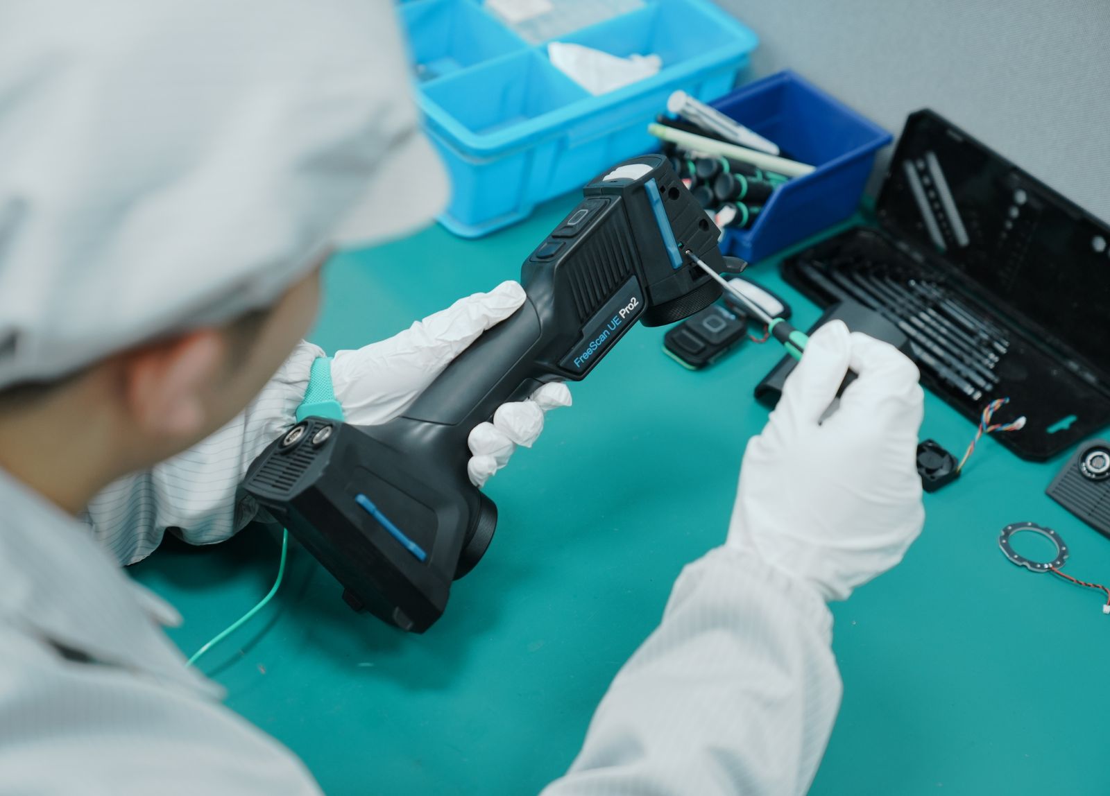
The current product listing for this tracking family is the FreeScan Trak ProW+. Buyers specifying a new system should confirm which configuration and software bundle is being quoted, because the tracking unit, handheld module and inspection software options determine what the acceptance test actually covers.
A verification checklist for buyers reading any field case
The Thai installation is useful as a template for what to ask — whether the case comes from SHINING 3D or from another supplier.
- Confirm the record's boundaries. How many units, how long in service, which parts, which tolerances. A single unit over one year is credible evidence of fit; it is not a benchmark.
- Ask for the calibration certificate, not the accuracy claim. Check the standard cited (ISO 10360-12/-13 or VDI/VDE 2634 Part 2/3), the issuing laboratory's accreditation, the serial number covered and the certificate date.
- Separate the time claim from the accuracy claim. A 60% or 5–10x time improvement says nothing about measurement uncertainty. Ask for both, and for the scope each was measured under.
- Run an acceptance test on your own parts. Include a representative mould with the hardest surface condition you actually have — dark, reflective or coated — and check repeatability by measuring the same feature twice.
- Check software continuity. Confirm that the inspection software you already use is supported (SHINING3D Inspect, PolyWorks, GOM Inspect and Geomagic Control X are commonly cited), and that reports can be archived in a form your quality system accepts.
- Confirm the support route and lead time. Remote versus on-site support, the spare-part path, and whether calibration can be performed locally or requires the unit to travel.
Outlook
The next step for this kind of evidence is longitudinal rather than promotional. If the same unit's calibration records, per-part cycle times and scan-to-CAD comparisons were tracked across successive years, a mould shop could read wear trends from its own data rather than from operator experience, and a supplier's capability claim would rest on a series instead of a snapshot.
For now, the defensible reading of the Thai case is conditional and specific: a single FreeScan Trak ProW has been in inspection use at an industrial machinery manufacturer in Thailand for more than a year, it reduced per-part inspection from 30–45 minutes to 10–15 minutes, and its output feeds CAD/CAM comparison work supporting reverse engineering, quality inspection and design validation. Whether a different mould shop sees a comparable result depends on part size, feature count, surface condition and the tolerance band being signed off — which is precisely what an acceptance test is designed to establish.
FAQ
What does the Thailand deployment actually demonstrate about SHINING 3D's capability?
It demonstrates that one FreeScan Trak ProW unit has been used for more than a year by an industrial machinery manufacturer in Thailand to inspect high-precision moulds and customised industrial equipment, with per-part inspection falling from 30–45 minutes to 10–15 minutes and overall 3D inspection efficiency improving by approximately 60%. It is evidence of fit in one real production setting, not a benchmark that applies to every mould application.
How is accuracy certified and made traceable for a metrology 3D scanner?
SHINING 3D issues calibration and accuracy certificates against VDI/VDE 2634 Part 2 and Part 3 and against ISO 10360-12 and -13. Its accuracy laboratory is accredited to ISO/IEC 17025 by CNAS, and because CNAS participates in mutual recognition arrangements such as the ILAC MRA, those calibration certificates are recognised internationally. Traceability therefore rests on the certificate's standard, issuing laboratory, serial number and date, rather than on a headline accuracy figure quoted in a brochure.
What customisation and integration options apply to mould inspection workflows?
SHINING 3D's recorded capability terms are OBM and ODM production with logo and automation-solution customisation, a minimum order of one unit, and a 30–45 day lead time. On the software side, scan data is used within CAD/CAM workflows for reverse engineering, quality inspection and design validation, and inspection platforms commonly cited for this work include SHINING3D Inspect, PolyWorks, GOM Inspect and Geomagic Control X.
How long does implementation take, and what support follows installation?
Lead time is recorded at 30–45 days, with 100% testing before shipment and acceptance structured either as delivery inspection or as post-installation acceptance. After-sales support is provided both remotely and on site. Because acceptance can be tied to post-installation performance, the practical implementation period includes the buyer's own verification on representative parts, not only the delivery date.
What should a buyer check before treating a supplier case study as capability evidence?
Check the number of units, the length of service, the parts and tolerances involved, and whether the reported figures separate time savings from accuracy. Ask for the calibration certificate behind the accuracy claim, confirm which software and configuration the quoted system includes, and require an acceptance test on your own hardest-to-measure mould before signing off. A case describes what happened at one site; an acceptance test describes what will happen at yours.
Tem questões ou precisa de mais detalhes?
Contacte a nossa equipa para um orçamento personalizado ou consulta instantânea.
Solicitar orçamento
Preencha o formulário abaixo e a nossa equipa entrará em contacto com uma proposta personalizada.
Chat direto do WhatsApp
Prefere conversar em tempo real? Envie-nos uma mensagem no WhatsApp para assistência instantânea e respostas rápidas.
- Obter orçamento personalizado
- Partilhar fotos ou documentos
- Discuta as suas necessidades diretamente
Geralmente responde em 5–30 minutos durante o horário de expediente.