
Flare System Technical FAQ: Turndown, Temperature, Materials
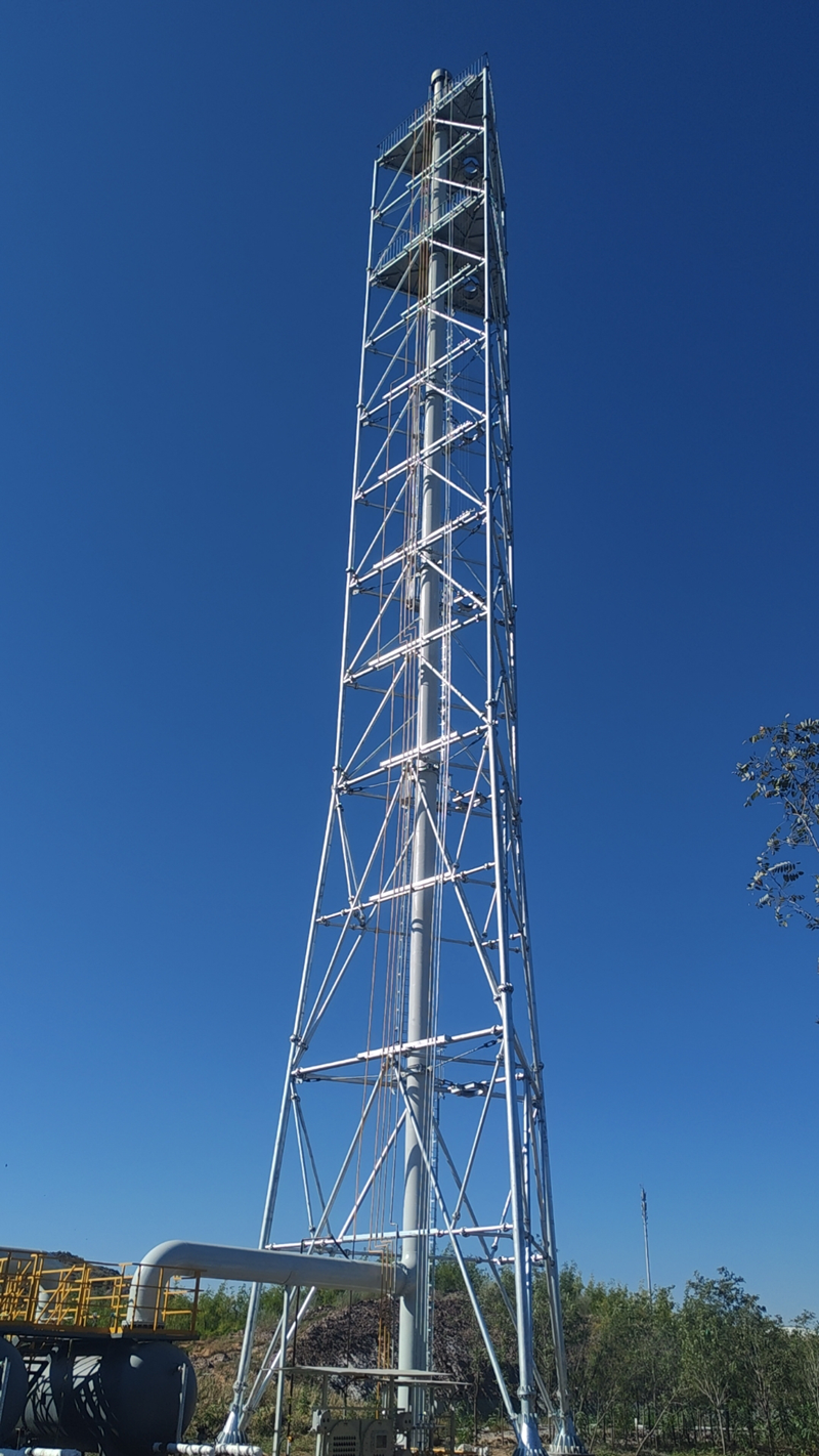
Flare systems spend most of their service life idle and are judged on the day they are not. That is why technical procurement reviews rarely approve a flare quotation without returning to three questions: how far the system can turn down before combustion becomes unstable, what temperature the equipment is genuinely engineered to withstand, and which alloy is used in which zone of the structure.
The three answers are interdependent, which is why they cannot be evaluated in isolation. A turndown figure quoted without a gas composition is a claim. A maximum temperature quoted without a duration is a peak. A material list quoted without the zone it applies to is a shopping list. Buyers who separate these questions tend to end up comparing bids that look similar on paper while describing materially different equipment.
Shandong Zexuan Environmental Protection Technology Co., Ltd. is a manufacturer and engineering service provider established in 2015, based in Shandong, China, specialising in industrial flare systems, thermal treatment equipment and waste gas combustion solutions. The company operates a 24,100 m2 manufacturing base with more than 80 employees, including 30+ engineering and technical specialists, and its export business covers more than 10 countries across the Middle East, Central Asia, Southeast Asia, Africa and Russia. The technical parameters discussed below are those published for its flare and combustion product lines.
Why these three questions surface at the decision stage
Flaring volumes provide the context. Global gas flaring reached 151 billion cubic meters in 2024, the highest level recorded since 2007, according to World Bank flaring data. In parallel, the global flare systems market is valued at approximately USD 4.8 billion in 2025, a figure supported by regulatory pressure on hydrocarbon emissions and a recovery in oil and gas investment.
Both signals push procurement teams toward equipment that can be defended in an audit, not merely installed. That is the point at which turndown, temperature and material selection stop being manufacturing details and become commercial risk. A flare that cannot hold a stable flame at low flow either releases unburned hydrocarbon or forces operators into continuous venting. A flare whose temperature envelope has been overstated fails at the tip or the refractory. A flare with the wrong alloy in the wrong zone fails at the weld — usually after the warranty period.
The practical consequence for buyers is that a flare quotation should be read as a set of conditional statements. Each number is valid only inside the gas composition, pressure, flow range and site conditions it was calculated for. The remainder of this article answers the questions that determine whether those conditions are stated clearly enough to compare.
Turndown ratio: what is actually being specified
Turndown ratio describes the relationship between the highest gas flow a flare system is designed to handle and the lowest flow at which it still burns stably. It is not a property of a flare tip in isolation. It is the combined outcome of tip geometry, assist mode, gas heating value, supply pressure and control philosophy.
The reason turndown dominates so many procurement discussions is that real plants rarely present a single flow condition. Three application profiles illustrate how different the requirement becomes:
- Petrochemical and chemical processing plants treat process off-gases and emergency vent gases in continuous or emergency standby modes. The gas stream can combine high-pressure methane, low-flow intermittent vent gas, variable-pressure exhaust and toxic or hazardous components in the same system.
- Landfill gas, biogas plants and waste-to-energy facilities combust methane at low pressure with a variable flow rate and continuous gas generation, which means the flare must stay lit across slow, persistent fluctuations rather than short upsets.
- Natural gas pipelines and compressor stations require controlled combustion of natural gas during pipeline maintenance, commissioning and emergency release, under high-pressure methane, low-flow intermittent vent gas and open-air conditions.
These are three different turndown problems wearing the same name. A design optimised for a continuous low-pressure biogas stream is not automatically suitable for an intermittent high-pressure relief event, even if both systems are described as having wide turndown.
How turndown is actually achieved
Wide turndown is normally delivered through tip design and operating mode rather than through a single fixed orifice. The ZX-FT Series flare tip is designed for smokeless, sonic, air-assisted and Coanda operation, with primary materials including Inconel 625, SS310S and SS316L, a maximum operating temperature of 1100 degrees Celsius, and customizable diameter and gas capacity for hydrocarbon gases in refinery, petrochemical, LNG and oil and gas processing industries.
Staging is the other lever. A ground flare system installed for coalbed methane vent gas in China uses a three-stage venting design with PLC automatic control at a processing capacity of 90 x 10^4 Nm3/d, and has been in operation for more than two years with stable methane combustion. Staging allows the system to bring combustion capacity online in steps rather than forcing a single burner to cover the entire flow range.
Operating temperature: reading 1100 degrees Celsius and 800-1200 degrees Celsius correctly
Published temperature figures for flare and combustion equipment describe component operating envelopes, not a promise about the temperature of the steel a technician can touch. The published values across the Zexuan product lines illustrate how the envelope shifts with equipment type.
| Equipment | Published operating envelope | Primary thermal concern |
|---|---|---|
| ZX-FT Series flare tip | Up to 1100 degrees Celsius | Tip oxidation, thermal cycling and flame stability |
| ZX-EGF Series enclosed ground flare | 800-1200 degrees Celsius | Refractory lining integrity and shell temperature control |
| ZX-TO / ZX-RTO / ZX-RCO thermal oxidizers | 800-1200 degrees Celsius | Combustion chamber and ceramic heat storage media |
| ZX-INC hazardous waste incineration system | 850-1200 degrees Celsius | Refractory performance under multi-stage combustion |
Three clarifications matter more than the numbers themselves.
First, the number belongs to a component. The ZX-EGF Series enclosed ground flare uses a low-radiation design with a refractory lining, and its 800-1200 degrees Celsius envelope describes the combustion zone, not the external structure. The refractory lining is what allows the outer shell to be built from carbon steel.
Second, duration matters. A continuous operating temperature and a short upset peak are different requirements, and a quotation that lists only one figure should be questioned. Temperature monitoring and operation guidance, together with structural design that accounts for thermal expansion, are part of how this is managed in practice.
Third, temperature is an outcome, not a setting. Flare temperature follows from gas composition, heating value and flow. A buyer specifying an operating temperature without specifying the gas analysis is effectively specifying an untested condition.
Material choices: Inconel 625, SS310S, SS316L and carbon steel
Material selection in a flare system follows a simple logic that is often obscured by grade lists: each alloy is assigned to the zone where its dominant failure mechanism occurs. The published material options across the product lines reflect that logic.
| Material | Typical zone in the system | Reason it is selected |
|---|---|---|
| Inconel 625 | Flare tip region | Oxidation resistance and mechanical strength at the highest temperature with repeated thermal cycling (ZX-FT Series) |
| SS310S | High-temperature zones | Heat resistance under sustained elevated temperature exposure (ZX-FT, ZX-EGF, ZX-INC) |
| SS316L / SS304 | Corrosive or moderate-temperature components | Corrosion resistance against acidic gas, moisture and harsh environments (ZX-EGF, ZX-TO/RTO/RCO) |
| Carbon steel | Structural shell and lower-temperature sections | Mechanical strength where refractory protection separates the steel from the flame (ZX-EGF, ZX-INC) |
| Refractory materials | Enclosed ground flare and incinerator internals | Thermal barrier between the combustion zone and the steel shell (ZX-EGF, ZX-INC) |
The ZX-FT Series flare tip lists Inconel 625, SS310S and SS316L as its primary materials, which is a compact illustration of the zoning principle: a nickel alloy where the flame attaches, a heat-resistant stainless grade in the high-temperature path behind it, and a molybdenum-bearing stainless grade where corrosion rather than temperature governs.
Corrosion is the mechanism that most often overrides a temperature-based material selection. Acidic gas, moisture and harsh ambient environments attack welds and low-velocity zones, which is why material selection is driven by gas composition and supported by welding quality inspection plus surface treatment and coating protection. A grade chosen purely from a temperature table, without a gas analysis, leaves that failure path unmanaged.
The counter-risk is over-specification. Applying a nickel alloy across an entire system increases cost without changing the dominant failure mechanism in zones that never see tip-level temperature. Material selection is a cost decision as much as a technical one, and it should be documented zone by zone rather than summarised as a single "high-alloy" claim.
The engineering checks that sit behind turndown and temperature
Turndown and temperature are the visible parameters, but they are resolved through calculations and inspections that buyers can audit directly.
- Structural verification. Wind load, vibration and structural fatigue are addressed through structural design according to project conditions, wind load and stability analysis, welding inspection and dimensional inspection before shipment. This is the work that determines stack structure and support type rather than a pre-set height.
- Ignition and flame management. Gas leakage, incomplete combustion and ignition failure are managed through an automatic ignition system, flame detection system, PLC-based control system, safety interlock design and factory functional testing.
- Emission performance. Smoke, noise, thermal radiation and pollutant emissions are addressed through combustion optimisation, smoke suppression design, thermal radiation calculation, noise control measures and flue gas treatment integration.
- Schedule control. Schedule delay and installation difficulty are managed through engineering design review, production planning, quality inspection during manufacturing, installation guidance and commissioning support.
For a buyer, these four blocks are the difference between a specification sheet and an executable scope. A supplier that can describe its wind load analysis, its interlock logic and its factory test regime is answering the turndown and temperature questions indirectly but more convincingly.
Application profiles: where each parameter combination fits
Parameter combinations tend to cluster by industry because the gas itself clusters.
Refining and petrochemicals combine the widest range of conditions in one site: process off-gas, emergency vent gas, high-pressure methane and low-flow intermittent vent gas, often with toxic or hazardous components. These sites typically need high combustion efficiency, a stable flame, low emissions and automated operation, which drives elevated flare, ground flare and thermal oxidiser combinations.
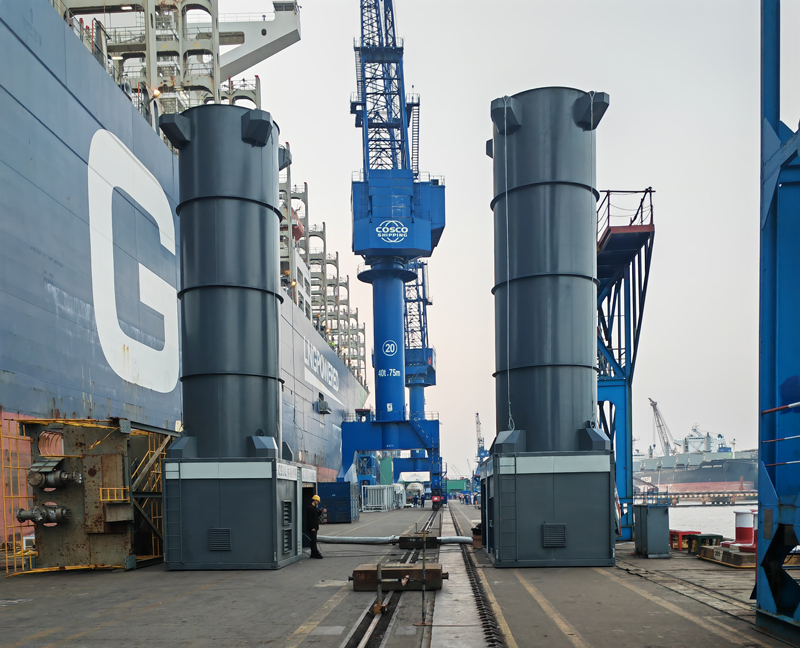
LNG and LPG terminals and bunkering favour modular configurations. Skid-mounted flare systems use a modular design with faster installation and easier relocation than conventional field-built systems, lower installation cost from reduced site construction work, and easier replacement and maintenance through an integrated skid structure. Typical duty covers terminal and bunkering boil-off gas treatment, waste tyre pyrolysis, plastic pyrolysis projects, remote industrial sites and temporary gas treatment applications.
Landfill gas and biogas plants operate at low pressure with variable flow and continuous generation, and require automatic ignition, stable combustion and outdoor reliability, supported by a flare stack, blower, ignition system and monitoring system.
Metallurgy, steel and heavy industry treat high-temperature exhaust gas, dust-containing gas and industrial combustion emissions continuously, with high-temperature resistance, heavy-duty operation and long service life as the defining requirements.
Field evidence across these profiles includes a coalbed methane ground flare operating for more than two years at 90 x 10^4 Nm3/d with three-stage venting and PLC control; two flare systems treating DL-Methionine process vent gas in China with more than one year of stable operation; three flue gas treatment units running for over a year at a South Korean tyre pyrolysis plant; and a skid-mounted ground flare completed within one year for a plastic pyrolysis project in Vietnam.
Market trend: what is changing in flare procurement
Several market signals point in the same direction. The global flare systems market is valued at approximately USD 4.8 billion in 2025, driven by regulatory pressure and recovering upstream investment. The totally enclosed ground flare segment was valued at USD 113 million in 2024, with growth attributed to destruction efficiencies exceeding 98 percent. The wider VOC control systems market, including thermal oxidisers and incinerators, is estimated at USD 7.5 billion in 2025, with China identified as a key growth market at a 5.4 percent CAGR.
Regionally, Asia-Pacific holds a 35 percent share of the flare gas recovery system market as of 2025, the largest regional share globally. The competitive landscape is concentrated among established combustion specialists, with Zeeco, John Zink Hamworthy (Koch), Honeywell UOP and Baker Hughes identified as major global competitors in the flare and combustion segment.
The procurement implication is straightforward. As emission performance becomes measurable, buyers increasingly ask suppliers to demonstrate destruction efficiency and operating envelopes rather than describe capability in general terms. Suppliers positioned to answer with documented parameters benefit; those relying on brand familiarity alone face longer technical reviews.
How flare systems compare with traditional and alternative solutions
| Decision axis | Traditional or alternative option | What project-tailored equipment changes | Boundary condition |
|---|---|---|---|
| Equipment basis | Standardised flare equipment with fixed universal specifications | Design tailored to gas flow, composition, pressure, temperature and site conditions, with optimised combustion efficiency | Higher engineering input at the front end |
| Gas disposal | Direct gas venting | Controlled combustion converts combustible gas into controlled combustion products, with destruction efficiency typically at or above 98 percent depending on system design | Higher equipment investment; routine inspection still required |
| Radiation and noise | Open elevated flare | Enclosed ground flare delivers lower thermal radiation, lower noise and reduced visual impact, with similar combustion efficiency when properly designed plus better emission control and operational stability | Higher initial investment; ground-level access for maintenance |
| Installation | Conventional field-built fixed flare | Skid-mounted modular design shortens installation time and lowers installation cost through reduced site work | Best suited to modular, remote or temporary duty rather than very large field-erected structures |
| VOC and thermal treatment | Conventional combustion equipment | RTO systems reach VOC destruction efficiency up to 99 percent or higher, with PLC control reducing manual intervention and heat recovery options improving energy utilisation | Higher initial investment offset by compliance performance |
Two boundaries deserve to be stated plainly, because they are frequently blurred in procurement discussions.
First, project-tailored design is not automatically the correct answer for every site. A stable, simple, low-variability gas stream that matches a standard configuration does not gain much from engineering customisation, and the additional front-end engineering input delays delivery without changing the operating outcome. Customisation earns its cost where gas composition, flow range or site conditions fall outside standard envelopes.
Second, controlled combustion destroys gas rather than recovering it. A flare system, including an enclosed ground flare with high destruction efficiency, converts combustible gas into combustion products; it does not capture the energy value of the stream. Where recovery economics are the primary objective, flare gas recovery is a separate decision with a different equipment set. Flare systems remain safety and compliance equipment, and they should be specified as such.
Limits and boundaries buyers should accept before ordering
- Turndown, stack structure, radiation envelope and material zoning are outputs of project data. Any figure published without the corresponding gas analysis, pressure case and assist mode is indicative only.
- Higher engineering input is a real cost item in project-tailored designs, and it should be weighed against the variability of the actual gas stream.
- Enclosed ground flare systems carry higher initial investment than open elevated flares; the return comes from lower environmental impact and easier compliance, not from lower capital cost.
- Skid-mounted systems suit modular, remote and temporary duty. They do not replace large field-erected structures where scale and height govern the design.
- Controlled combustion requires routine inspection and depends on reliable ignition, flame detection and interlock performance. These are operating commitments, not one-time purchase features.
- API 521 governs pressure-relieving and depressuring system design, including a minimum flare header slope of one quarter inch per ten feet for drainage. Compliance with the standard defines design requirements; it does not validate performance for a specific gas composition.
Future outlook
The direction of the category is toward verifiable performance rather than broader capability claims. Three currents are visible.
Low-carbon combustion technology is shifting the emphasis from destroying gas to controlling what leaves the stack, which places more weight on measured destruction efficiency and continuous monitoring. Intelligent control systems are changing how turndown is managed in practice, because PLC-based sequencing and flame detection allow operating modes to be switched automatically as flow changes rather than relying on operator judgement. Flare gas recovery and digital operation solutions are moving the boundary between safety equipment and process equipment, creating a market where the flare remains the final barrier but is no longer the only pathway considered.
For buyers preparing projects under tightening emission expectations, the practical response is to request parameter-level documentation at the tender stage: maximum and minimum flow, continuous and peak temperature, material grade by zone, and the calculation basis for structure and radiation. Those four items convert a quotation into a comparable technical offer.
Frequently asked questions
1. What does turndown ratio mean for a flare system, and how should it be confirmed before ordering?
Turndown ratio is the relationship between the maximum gas flow a flare system is designed to handle and the lowest flow at which combustion remains stable. It results from tip geometry, assist mode, gas heating value, supply pressure and control philosophy acting together rather than from a single component. Because real operating cases differ widely, the ratio should be confirmed against a specific gas composition and pressure case. A practical check is to ask for the maximum design flow and the minimum stable flow as separate values, each linked to the operating case it describes.
2. What operating temperature should I specify for an elevated flare system?
Operating temperature should be derived from the gas analysis, not selected from a preference list. Published envelopes differ by equipment type: the ZX-FT Series flare tip operates at temperatures up to 1100 degrees Celsius, while the ZX-EGF Series enclosed ground flare and the ZX-TO, ZX-RTO and ZX-RCO thermal oxidisers operate between 800 and 1200 degrees Celsius, and the ZX-INC hazardous waste incineration system between 850 and 1200 degrees Celsius. Buyers should also establish whether a stated figure represents continuous operation or a short-term peak, and what duration applies.
3. Why are Inconel 625 and SS310S used in different parts of the same flare system?
Different alloys are assigned to different failure mechanisms. The ZX-FT Series flare tip lists Inconel 625, SS310S and SS316L as primary materials, reflecting a typical zoning logic: a nickel alloy at the tip where the highest temperature and repeated thermal cycling occur, a heat-resistant stainless grade such as SS310S in sustained high-temperature zones, and SS316L or SS304 where acidic gas and moisture create corrosion risk at moderate temperature. Selection is driven by gas composition and is supported by welding quality inspection and surface treatment.
4. How does an enclosed ground flare compare with an open elevated flare in measurable terms?
An enclosed ground flare offers lower thermal radiation, lower noise and reduced visual impact, with similar combustion efficiency when properly designed, and provides better emission control and operational stability. Thermal radiation and noise can be controlled to meet project requirements, and maintenance access is at ground level. The ZX-EGF Series enclosed ground flare operates between 800 and 1200 degrees Celsius with combustion efficiency up to 99.9 percent, a low-radiation design, a refractory lining and material options covering carbon steel, SS304, SS316L and SS310S. The trade-off is higher initial investment, with the return coming from reduced environmental impact and easier regulatory compliance.
5. When is a skid-mounted flare system a better procurement choice than a field-built structure?
Skid-mounted flare systems use a modular design that allows faster installation and easier relocation than conventional field-built systems, with lower installation cost through reduced site construction work and easier replacement and maintenance via the integrated skid structure. They are well matched to terminal and bunkering LNG/LPG boil-off gas treatment, waste tyre pyrolysis plants, plastic pyrolysis projects, remote industrial sites and temporary gas treatment applications. They are not a substitute for large field-erected structures where site conditions, capacity and height drive the design.
6. What should a buyer verify in a flare system datasheet before placing an order?
A datasheet should state the maximum and minimum gas flow, gas composition, supply pressure and temperature basis; the material grade assigned to each zone; the applicable turndown and assist mode, whether smokeless, sonic, air-assisted or Coanda; and the structural basis, including wind load and stability analysis, welding inspection and dimensional inspection before shipment. The control scope should identify the automatic ignition system, flame detection system, PLC-based control system and safety interlock design, and should confirm factory functional testing before delivery.
7. Does compliance with API 521 answer the technical questions in a flare procurement review?
API 521 governs pressure-relieving and depressuring system design and specifies requirements such as a minimum flare header slope of one quarter inch per ten feet for drainage. It defines the design framework, header arrangement and relief philosophy, but it does not validate performance for a specific gas composition, flow range or site condition. Buyers should treat standard compliance as the baseline and require project-specific data on turndown, temperature envelope and material zoning to complete the technical evaluation.
8. Which material choices handle corrosive or acidic flare gas?
Corrosion caused by acidic gas, moisture or harsh environments is managed through material selection based on gas composition, the use of stainless steel and high-temperature alloys when required, welding quality inspection, and surface treatment and coating protection. In practice this means grade selection follows the gas analysis rather than the nominal temperature alone, because acidic components and moisture attack welds and low-velocity zones where temperature is not the governing factor. Systems exposed to both high temperature and corrosive media typically require separate material decisions for the tip zone and the downstream wetted components.
Consolidated product parameters and configuration options for flare systems and thermal treatment equipment are compiled in the Zexuan company brochure.