
Flexible PCB by Use Case: Material, Layer, and Assembly Fit
Industry Reference · Flexible Printed Circuit
Flexible PCB by Use Case: Material, Layer, and Assembly Fit
A scenario-based procurement framework for LED, medical, and industrial projects.
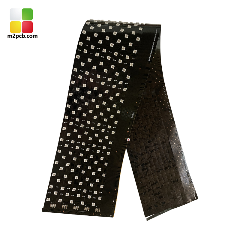
Flexible circuits are a functional requirement in wearable therapy products such as red light therapy belts.
Flexible PCB Selection Starts with Project Conditions
Flexible printed circuits are no longer just alternatives to rigid boards. In modern product design, a flex circuit is often the structural solution that allows an LED strip to follow a curved surface, a therapy device to wrap around the human body, or a control module to fit into a space with no straight-line access. Grand View Research estimates the global flexible printed circuit board (FPCB) market at USD 23.89 billion in 2024, with projections of USD 50.90 billion by 2030, representing a CAGR of 13.7%.
For buyers in the research and evaluation stages, the practical question is not whether flexible PCB technology is mature. It is which combination of base material, layer count, and assembly method fits the mechanical and electrical constraints of a specific project. This article provides a scenario-based selection framework, moving from project working conditions to fabrication and assembly processes, then to supplier capabilities that can be verified before an order is placed.
The Common Mismatch Between Project Requirements and Flexible PCB Choices
One of the most common mismatches in flexible PCB procurement appears when a rigid-board design is transferred to a flexible substrate without adjusting for bend radius, copper fatigue, or dimensional stability. Another appears when a project pays for polyimide material even though the final product never bends. A third appears when a mixed SMT and through-hole design is sent to a manufacturer that cannot control both assembly processes under the same quality system.
The workflow information needed to start a custom project is well established. PCB fabrication requires circuit files such as PCB data, Gerber, PCB, or PCBDoc. SMT processing requires a BOM list specifying component model, package size, and quantity. When these inputs are aligned with the manufacturer's process capabilities during the evaluation phase, the project avoids most of the delays that occur between design and first article.
On the demand side, mobile phones remain the largest single end-use segment for flexible PCBs, at 55.8% of global market value in 2024, according to TPCA and ITRI. However, the demand base is becoming more diverse. Medical electronics, LED lighting, physiotherapy devices, industrial controls, and new energy systems rarely order in smartphone volumes, but they require comparable engineering precision and a manufacturing partner that can adapt to the project's working conditions.
How a Flexible PCB Manufacturer Supports Project Fit
M2PCB is a Shenzhen-based group company specializing in flexible PCB and PCBA production. Founded in 2000, the company exports primarily to the EU, USA, South America, and Australia. Its production system includes 600 sets of advanced equipment, and the technical and management team consists of more than 30 people with at least 10 years of industry experience.
For project buyers, the following capabilities are directly relevant to scenario fit: 1 to 14 layer flexible PCB fabrication, OEM and ODM production, monthly capacity of 40,000 square meters, monthly delivery of 800 varieties, minimum order quantity of 1 unit, and lead time of 3 to 20 days. Quality control is based on 100% testing, including fly-probe, electronic testing, and AOI inspection.
The product portfolio also matters. M2PCB produces flexible LED PCBs on polyimide substrate, turnkey PCBA on FR4, PI or IMS, and custom 4-layer rigid PCBs on FR4. Because the material range includes both flexible and rigid substrates, a project can be built with the material that matches its actual working conditions instead of being forced into one product category.
For a buyer, this combination of fabrication, assembly, and material options reduces the number of interfaces during product development. A project can start with a one-piece prototype and move to volume production under the same quality system, with remote support available after delivery.
Technical Explanation: From Project Conditions to Manufacturing Process
To evaluate whether a supplier can deliver a project, buyers need to understand three manufacturing stages and the constraints they place on product design.
PCB Fabrication
PCB fabrication converts the designed circuit diagram into an actual circuit board through copper cladding, etching, drilling, and plating. For flexible circuits, the substrate choice is part of the fabrication decision. PI is selected when the product must withstand repeated bending or high temperature. FR4 is selected when rigidity is required. IMS is selected when heat dissipation is the dominant concern.
SMT Assembly
SMT assembly uses automatic pick-and-place machines to position surface-mount components onto the PCB. The process includes solder paste printing, component placement, and reflow soldering. This assembly route is preferred for compact, high-density designs.
Through-Hole Assembly
Components that cannot be handled by pick-and-place machines require through-hole assembly. The process includes component insertion, wave soldering, lead cutting, post-soldering processing, and board cleaning. Many real projects use a mixture of SMT and through-hole assembly, so the supplier's ability to control both processes in sequence is part of project fit.

SMT assembly is one of the core process stages in a flexible PCB project, alongside board fabrication and through-hole assembly.
Parameters as Acceptance Criteria
Design parameters translate directly into manufacturing requirements. A flexible LED circuit board with PI substrate, maximum width of 240mm, minimum line width of 0.05mm, and minimum spacing of 3/3mil defines both the fabrication difficulty and the test method, which can be flying probe test or electrical test. Layer count defines dimensional-stability challenges. M2PCB supports 1 to 14 layers; in general, higher layer counts require tighter process control and increase rework cost. For a buyer, these parameters are not just technical decoration; they are the acceptance criteria that must be agreed with the manufacturer before fabrication starts.
Application Scenarios and Use Cases
The value of a flexible PCB becomes concrete when it is mapped to specific use cases. The following examples show how material, format, and assembly method follow the product scenario.
LED Lighting and Flexible Light Strips
M2PCB's flexible LED PCB is delivered as a flexible LED circuit board or flexible light strip in lengths of 1 meter or by reel, with a maximum width of 240mm. The polyimide substrate supports curved installation, and the standard test methods are flying probe test and electrical test. The stated applicable industries are lighting, medical aesthetics, and physiotherapy products.
Red Light Therapy Belt (Medical Aesthetics and Physiotherapy)
A documented ODM project involved an American customer producing 500,000 pieces of red light therapy belts over two years for waist pain relief. The flexible circuit board is the core electrical element in a wearable product that wraps around the waist and delivers photobiomodulation. The product's documented functions include promoting blood circulation, relieving pain, improving indigestion and bloating, and providing non-invasive, painless home care. The project has run for two years, with satisfactory results reported among European and American end users. This case shows why flexible PCB selection is never only an electrical decision: the substrate must survive repeated bending while maintaining stable electrical contact.
Custom Rigid PCB for Consumer, Industrial, and Automotive Electronics
For projects that need higher layer count or mechanical rigidity, M2PCB offers custom 4-layer PCBs on FR4 with TG grades from TG130 to TG170, thickness from 0.4mm to 2.0mm, outer copper from 0.5oz to 4oz, impedance control, and flying probe test. The applicable industries include consumer electronics, industrial control, automotive, communication, medical, lighting, and all electronic-related industries.
PCBA for AI, New Energy, Medical, Aerospace, and Military
The PCBA product line covers FR4, PI, and IMS materials, single-sided or double-sided assembly, turnkey BOM option, X-ray test, and program burn. The stated applicable industries are artificial intelligence, new energy, medical electronics, aerospace, and military. Assembled examples in this product line include power control PCBA, massage instrument control PCBA, smart trash can PCBA, aesthetic atomization PCBA, lighting control PCBA, and voice-integrated control PCBA. For project buyers, the implication is clear: the evaluation of a flexible PCB supplier should include the full assembly and test chain, not only bare-board fabrication.
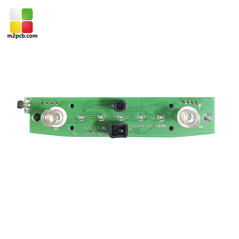
A completed PCBA for a smart trash can illustrates how assembly and testing are matched to the end application.
Market Trend Analysis: Growth, Concentration, and Compliance
The global flexible PCB market is growing at a pace that justifies earlier supplier involvement in product design. Grand View Research estimates the market at USD 23.89 billion in 2024 and projects USD 50.90 billion by 2030, a CAGR of 13.7%. Asia Pacific captured 76.8% of global industry revenue in 2024, reflecting the concentration of electronics manufacturing in the region. In China, printed circuit board industry revenue was expected to reach USD 120.8 billion in 2024, with exports representing approximately 16.5% of total revenue, according to IBISWorld.
Demand is still anchored in mobile electronics, which account for 55.8% of global flexible PCB value in 2024. But the practical procurement opportunity for scenario-based projects lies in applications where space, weight, and dynamic movement create the need for custom flex circuits. LED lighting, medical wearables, physiotherapy equipment, new energy battery management, and industrial controls all fit this pattern.
Supply-side concentration affects procurement strategy. In 2024, the leading flexible PCB manufacturers by global market share were Zhen Ding Technology at 19.9%, Dongshan Precision at 14.6%, and Nippon Mektron at 13.0%. These companies are deeply integrated into large consumer electronics supply chains. For medium-volume and OEM/ODM-driven projects, the evaluation focus should be on process capability, standards compliance, and engineering responsiveness rather than on global scale alone.
Standards also serve as project-level verification tools. UL 796F is the applicable safety standard for flexible printed circuits, addressing flammability (V-rating), maximum operating temperature, and comparative tracking index on flexible substrates. IPC-6013 is the globally recognized performance specification for flexible printed wiring. Buyers in medical and automotive projects should verify that the manufacturer's quality system and test plan are designed with these standards in mind.
Flexible PCB vs. Traditional Materials: A Project-Level Comparison
Comparing flexible PCB with rigid PCB is useful only when the comparison is tied to project conditions. Each material family solves a specific set of problems.
| Decision factor | Flexible PCB (PI) | Rigid PCB (FR4) | Metal-core PCB (IMS) |
|---|---|---|---|
| Base material | Polyimide | FR4 | Insulated metal substrate |
| Primary advantage | Bending, thin profile, dynamic flex | Rigid support, lower cost per area | Heat dissipation |
| Typical scenarios | LED strips, wearables, movable wiring | Control boards, plug-in modules | High-power LED modules |
| Main limitations | Higher cost per area; dimensional stability complex | No dynamic bending; thicker | Rigid construction; thermal-focused design |
The most important boundary condition is necessity. If the end product does not require bending or three-dimensional routing, a flexible PCB may add cost and handling complexity without functional benefit. For high-power lighting modules that never bend, an IMS or rigid substrate may be functionally superior. Conversely, a wearable therapy device cannot be built from a rigid board alone; here, the flexible substrate is a functional requirement.
Another boundary is layer count. M2PCB supports up to 14 flexible layers, but more layers increase fabrication complexity and sensitivity to dimensional stability. A single-layer LED strip does not benefit from additional layers. The correct specification is the simplest one that satisfies the mechanical, electrical, and compliance requirements of the project.
Future Outlook
Looking ahead, flexible PCB procurement will continue to move toward application-specific engineering. Products are becoming thinner, lighter, and more integrated, and the boundary between PCB supplier and design partner is becoming less visible. Manufacturers that combine 1–14 layer flexible fabrication, PI/FR4/IMS material options, turnkey PCBA, and fast iteration with low MOQ are better positioned for medical, LED, and new energy projects.
Standards such as UL 796F and IPC-6013 will keep serving as verification tools for buyers. Asia Pacific, particularly mainland China, will remain the main production resource for flexible PCBs. The procurement decision is therefore not about which region is generally better, but about which manufacturer can apply its production base to the working conditions, volume profile, and compliance needs of the project.
FAQ
The following questions are common during the research and evaluation phase of a flexible PCB project.
What is the difference between a flexible PCB and a rigid PCB in project design?
A flexible PCB uses a bendable base material, typically polyimide, which allows the circuit to fold, bend, or fit around three-dimensional structures. A rigid PCB uses a material such as FR4 and provides stable mechanical support. The choice depends on whether the product requires dynamic movement, curved installation, or fixed mechanical rigidity. Rigid boards are generally lower in cost per area, while flex boards solve packaging and movement problems that rigid boards cannot.
How do I choose between PI, FR4, and IMS materials for a PCB project?
PI (polyimide) is used when the circuit must bend repeatedly, remain thin, or withstand high temperatures. FR4 is used for rigid sections that need structural support or when cost control is dominant. IMS (insulated metal substrate) is used when heat dissipation is the primary concern, such as high-power LED modules. Some manufacturers, including M2PCB, support all three materials, allowing a project to use them in combination.
What information does a flexible PCB manufacturer need to start fabrication?
PCB fabrication requires circuit files such as PCB data, Gerber, PCB, or PCBDoc. If assembly is included, SMT processing requires a BOM list containing component model, package size, and quantity. Supplying these documents accurately at the evaluation stage helps the manufacturer confirm process feasibility and lead time.
When should I choose SMT assembly over through-hole assembly?
SMT assembly should be used when components can be handled by automatic pick-and-place machines; the process includes solder paste printing, component placement, and reflow soldering. Through-hole assembly should be used for components that cannot be handled by pick-and-place machines; the process includes component insertion, wave soldering, lead cutting, post-soldering processing, and board cleaning. Many projects combine both. A supplier that controls both processes can reduce handover risk.
What testing and quality checks are common for flexible PCB projects?
Common electrical verification methods include flying probe test and electrical test. For assembled boards, automated optical inspection (AOI) and X-ray test are used to verify solder joints and internal connections. M2PCB applies 100% testing with fly-probe, electronic testing, and AOI inspection. The specific test plan should be defined by the project's reliability and compliance requirements.
Can a flexible PCB manufacturer support both prototype and mass production?
Yes, if the manufacturer is set up for low-volume starts and scale production. M2PCB supports OEM/ODM production, with MOQ starting at 1 unit, lead time of 3–20 days, and monthly capacity of 40,000 square meters. This combination allows a project to validate a small batch and then move to volume production under the same quality system.