
Flow Sensor Accuracy Explained: A Technical FAQ for OEM Engineers
Flow sensor accuracy is not a single number. In ultrasonic flow measurement, one product line can legitimately carry a percentage figure, an absolute flow figure and a measuring range in the same data sheet — and all three can be correct at the same time. For OEM engineers specifying sensors into medical devices, bioprocess equipment, semiconductor tools or liquid-cooling loops, the practical question is not which figure is right, but which figure governs the acceptance test for a particular configuration.
Shanghai Xunyin Technology Co., Ltd (XY-TEK) is a Shanghai-based developer and manufacturer of ultrasonic flow sensors and flow meters, founded in 2018 and focused on fluid management and control for small tubing and low flow rates. The company operates a 5,000 m² facility with a 30+ person R&D team and an annual output of more than 8,000 units, exports to global markets, and its portfolio covers clamp-on, in-line, single-use, low-flow, pulsatile and bubble-detection sensor designs. XY-TEK sensors are used in medical devices, bioprocessing, scientific research, industrial automation and food/beverage production.
This technical FAQ is written for the evaluation stage of a project. It explains what ratings such as ±0.1 mL/min and ±1% actually describe, how clamp-on and single-use measurement paths change the accuracy an engineer can expect, which documented figures apply to which series (SU, TGU, CG, CM, CS, CPD, TPD, TPK, TH and BG), and what evidence to request before a specification is frozen.
Why accuracy specifications get misread during evaluation
Three structural issues cause most of the confusion in sensor comparison exercises.
- The reference point is not always stated. Accuracy can be expressed as a percentage of the reading, a percentage of full scale, or an absolute flow value. Two sensors quoting “±1%” can behave differently if one means 1% of the measured value and the other means 1% of the top of the range.
- Accuracy is quoted for a measurement path, not for a chip. A clamp-on sensor measures through the tube wall; a single-use sensor measures inside a dedicated channel; an in-line sensor measures inside a fixed wetted body. The acoustic path belongs to the configuration, so the same sensing technology can produce different real-world tolerances in different installations.
- Range and scope are two different fields. A documented range describes the span the electronics can address; a working scope describes the span where the published accuracy is intended to hold. When only one of the two is quoted in a comparison table, the comparison is incomplete.
None of this is a specification defect. It becomes a problem only when the buyer assumes one meaning and the supplier designed for another — which is why the acceptance criterion, not the headline number, should be agreed in writing.
What ±0.1 mL/min and ±1% actually describe
XY-TEK documents the TGU Series low-flow ultrasonic flow sensor with a measurement accuracy of up to ±0.1 mL/min alongside a ±1% accuracy figure, over a documented range of 0–1000 mL/min and a working scope of 0.1–1000 mL/min. The two figures answer two different questions.
A percentage describes the error that scales with the measurement. An absolute value describes the floor below which the reading cannot be trusted regardless of flow. Read the arithmetic at two points on the TGU curve:
- At 100 mL/min, ±1% of reading is ±1 mL/min.
- At 1 mL/min, ±1% of reading is ±0.01 mL/min — a narrower interval than the documented ±0.1 mL/min floor.
In other words, near the bottom of the range the absolute figure is the more conservative number to design against, while the percentage figure governs the working span. Engineers specifying a dosing or dilution step should therefore state the setpoint at which the tolerance must hold, because a ±1% sensor at 500 mL/min and the same sensor at 0.5 mL/min represent very different control problems.
The same reading discipline applies to clamp-on series. The CG Series clamp-on ultrasonic flow sensor is documented with an accuracy field of ±3% over a 0–20 L/min range and a 0.02–20 L/min scope, while a separate headline figure of ±1% appears in the same series documentation alongside non-invasive measurement, bi-directional flow detection, air bubble detection and analog, pulse and RS485 outputs. Two figures attached to different fields of one specification are common in this category. The correct action is not to pick the more attractive number, but to ask which figure governs the acceptance test for the specific tubing, fluid and flow window in the application.
Documented accuracy and range by XY-TEK sensor series
The table below reproduces documented values from XY-TEK product data for the series most often shortlisted in OEM projects. It is organised to make the reference point visible, because that is the field that decides whether two sensors are actually comparable.
| Series | Measurement type | Documented accuracy | Documented range / scope | Fluid path |
|---|---|---|---|---|
| SU Series | Single-use ultrasonic flow sensor | ±2% | 0.05–10 L/min / 0.05–10 L/min | Single-use measuring channel, biocompatible polymer |
| TGU Series | Low-flow ultrasonic flow sensor | ±1%; measurement accuracy up to ±0.1 mL/min | 0–1000 mL/min / 0.1–1000 mL/min | U-shaped channel; PVC, silicone, PFA, PE, PUR tubing |
| CG Series | Clamp-on ultrasonic flow sensor | ±3% (accuracy field); ±1% headline figure | 0–20 L/min / 0.02–20 L/min | Clamp-on, flexible tubing OD 4–35 mm |
| CM Series | OEM clamp-on flow meter | ±3% | 0–30 L/min / 0.05–30 L/min | Clamp-on, OD 4–25 mm, RS485 output |
| CS Series | Clamp-on ultrasonic flow sensor | ±3% | 0–50 L/min / 0.1–50 L/min | Clamp-on, OD 6.4–25.4 mm, up to 90 °C |
| CPD Series | Clamp-on ultrasonic flow sensor | ±2% | 0–80 L/min / 0.1–50 L/min | Clamp-on, rigid plastic tubing OD 6–26 mm |
| TPD Series | In-line ultrasonic flow meter | ±2% | 0–1000 L/min / 0.5–100 L/min | In-line, DN15–DN50, PPS / stainless steel |
| TPK Series | In-line ultrasonic flow meter | ±2% | DN4–DN50 / 0.5–100 L/min | In-line, DN4–DN50, PPS / stainless steel |
| TH Series | Pulsatile / hemodynamic flow sensor | ±2% | 0–15 L/min / 0.01–15 L/min | Medical-grade polymer, precision ultrasonic chip |
| BG Series | Ultrasonic bubble detector | Detection sized to approximately 1/3 of tubing ID bubble | Customisable detection range | Clamp-on, OD 3.2–19 mm |
Two observations matter for procurement. First, the lowest documented accuracy figure in the range belongs to the TGU Series at ±1% with an absolute floor of ±0.1 mL/min — but that figure applies inside a narrow flow window measured in millilitres per minute, not to general-purpose liquid lines. Second, the widest flow spans (TPD and TPK, documented to 0–1000 L/min with a 0.5–100 L/min working scope) carry a ±2% figure, which reflects a different design priority: throughput and pressure loss rather than micro-volume resolution.
How the measurement path changes achievable accuracy
Clamp-on: accuracy depends on the tube
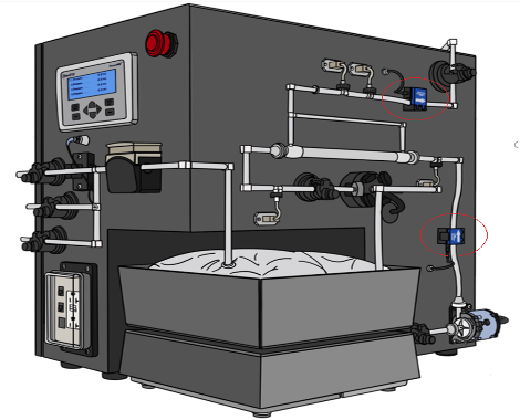
Clamp-on sensors sit outside the fluid path. XY-TEK describes the CG Series as compact, able to measure flow rate and output results without external circuitry, clamped directly onto flexible plastic tubing to measure liquid flow rate and detect air bubbles without contaminating the liquid. That non-contact architecture is the reason clamp-on designs are chosen for bioprocess, laboratory and medical device applications, and it is also the reason their accuracy depends on the tube: wall material, wall consistency, inner and outer diameter, and the stability of the acoustic coupling all sit between the sensor and the fluid.
Single-use: accuracy depends on the channel
The SU Series single-use ultrasonic flow sensor documents ±2% across 0.05–10 L/min, using a single-use measuring channel in biocompatible polymer materials and supporting hygienic fluid monitoring and sterile applications. Here the fluid path is a defined, replaceable component, so the acoustic geometry is fixed by the channel rather than by the tubing the user happens to install. For biopharma and single-use systems, that trade — one accuracy figure attached to one consumable channel — is often easier to qualify than a clamp-on figure that varies with tubing lot.
In-line: accuracy depends on the wetted body
In-line designs such as the TPD and TPK Series integrate the measuring section into the pipe. XY-TEK documents both at ±2% over DN15–DN50 and DN4–DN50 respectively, with PPS or stainless-steel bodies rated to 0–90 °C, no moving parts and low maintenance. They are typically selected where the fluid is continuously routed — industrial automation, battery manufacturing, chemical processing and liquid cooling — and where a permanently wetted, fixed geometry is preferable to a clamp-on assembly that has to be re-seated.
Pulsatile and bubble measurement are separate specifications
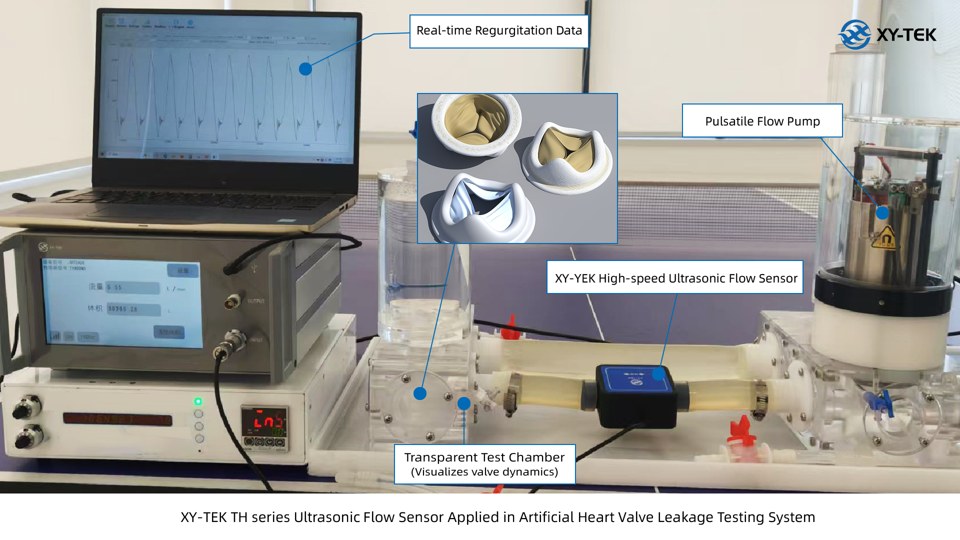
The TH Series pulsatile flow sensor documents ±2% over a 0–15 L/min range with a 0.01–15 L/min scope and is designed for high-speed pulsation capture in cardiovascular flow testing and hemodynamic work. The BG Series ultrasonic bubble detector is a different instrument class altogether: its specification is expressed as detection sized to approximately one third of the tubing inner diameter, with a customisable detection range. Engineers should not treat bubble detection as evidence of flow accuracy, or flow accuracy as evidence of reliable bubble detection — the two functions answer different questions in the same fluid line.
Installation, tubing and fluid conditions that move real accuracy
Documented accuracy is a conditional statement. The conditions that most often break it in practice are the ones listed in the same data sheets:
- Fluid cleanliness. XY-TEK documents its flow sensors for fluids containing no or few solid particles. Slurries, particulates and entrained solids are outside the intended envelope and should be filtered upstream.
- Tubing material. Clamp-on CG and CM Series are specified for flexible plastic tubing with smooth inner and outer surfaces — PVC, silicone, PFA, PE and PUR. The CPD, CS and BG Series are specified for rigid plastic tubing such as PFA, PTFE, Teflon, PVDF, PP and Nylon. A tube outside these lists invalidates the documented figure rather than degrading it gradually.
- Diameter match. Each series documents compatible outer and inner diameters — for example OD 4–35 mm / ID 2–25.4 mm for CG, OD 6–26 mm / ID 3–20 mm for CPD, DN15–DN50 for TPD. Tubing outside the documented bore range changes the acoustic path length and therefore the calibration.
- Fluid temperature. The documented window is 0–60 °C for CG, CM, SU, TGU, TH and BG, and 0–90 °C for CS, CPD, TPD and TPK. Temperature affects both the fluid and the tube, so a process running near the ceiling of a window deserves a stability check.
- Mounting stability. Because clamp-on measurement is non-invasive, the mechanical coupling between sensor and tube is part of the measurement chain. Repeatable mounting, consistent tube seating and stable tube routing support repeatable readings.
Three application patterns where accuracy requirements differ
Liquid cooling: trend accuracy rather than absolute accuracy
In coolant loops, XY-TEK ultrasonic flow sensors are used to monitor non-conductive coolant flow, prevent overheating, detect leaks and blockages, and optimise cooling efficiency. Reported deployments cover data centres, industrial equipment, medical device manufacturing and charging stations across the United States, China, Germany, Japan, Korea and Singapore, with typical service life of 2–4 years and reported outcomes including stable cooling performance, reduced energy consumption, extended equipment life, earlier anomaly detection and less downtime. The design priorities here are suitability for non-conductive media, non-invasive measurement, high stability, real-time monitoring, wide coolant adaptability and low pressure loss — a slow drift matters more than a small constant offset.
Battery electrolyte injection: contamination control dominates
In lithium-ion battery manufacturing, clamp-on ultrasonic flow sensors are used for non-invasive monitoring of electrolyte flow, supporting injection accuracy and detecting bubbles or leakage. XY-TEK reports clamp-on installation without breaking pipes, non-contact and contamination-free measurement, high compatibility with corrosive media and bi-directional measurement, with implementations across 10–30 production lines in China, the USA, Germany, Korea, Japan, India, Singapore and Thailand and stable operation for 2–3 years. Reported results include improved battery consistency, reduced rejection rate, low maintenance and enhanced production safety. The accuracy question here is really a contamination question: an in-line sensor that requires cutting the pipe introduces a risk that no accuracy figure offsets.
Electronics soldering flux: micro-flow and pulsation together
In electronics manufacturing and selective wave soldering, low-flow ultrasonic flow sensors are used for real-time measurement and control of pulsed micro-flux flow, bubble, blockage and leakage detection, and process data recording. XY-TEK documents ultra-low flow measurement down to 1 mL/min with ±1% accuracy, fast response for pulsating flow, no moving parts, corrosion resistance, maintenance-free operation, bi-directional measurement and standard connectors, with adoptions by electronics manufacturers, SMT/EMS factories and selective wave soldering equipment makers across the United States, China, Germany, Italy, France, the United Kingdom and the Netherlands over implementation periods of 1–3 years. Reported outcomes include improved soldering quality and consistency, fewer cold and missing solder joints, reduced flux waste and rework cost, and higher production yield.
Market trend: where accuracy requirements are tightening
Several published market estimates describe a category in expansion, which is one reason specification conversations have become more demanding.
- The global flow meter market was estimated at USD 10.64 billion in 2024 and is projected to reach USD 15.17 billion by 2030 (Grand View Research).
- The global ultrasonic flow meter market was valued at USD 1.52 billion in 2025 and is estimated to grow to USD 2.28 billion by 2031 (Mordor Intelligence).
- Asia Pacific held the largest regional share of the ultrasonic flow meter market in 2025 at 38.6%, driven by industrial expansion (Fortune Business Insights).
- The clamp-on ultrasonic flowmeter segment was valued at USD 1.25 billion in 2024, growing at a CAGR of 7.4% through 2032 (Global Information, Inc.).
- Flow control in the semiconductor industry was estimated at USD 5.83 billion in 2024, with a focus on high-purity fluid management (Market Research Future).
These figures should be used carefully. Published estimates for the ultrasonic flow meter market diverge substantially depending on scope — some include smart water metering, some exclude it — so a single number should not carry a business case on its own.
Two standardisation signals are more directly relevant to specification work. ISO 24062:2023 specifies requirements for clamp-on ultrasonic transit-time meters for liquids and gases in closed conduits, which gives buyers a shared vocabulary for that product class. EN ISO 13485 quality management systems apply to medical sensors, including flow sensors used in ventilators and drug delivery, which is why documentation practices in medical programmes often exceed what a general-purpose industrial purchaser expects.
The competitive field is broad. XY-TEK operates alongside established multinational suppliers such as Emerson Electric, Siemens AG, Endress+Hauser and Honeywell, which are widely listed among the major global players in ultrasonic flow measurement. Specialised manufacturers compete less on catalogue breadth than on low-flow resolution, single-use compatibility and configuration-specific documentation — which is exactly where buyers should direct their evaluation questions.
Clamp-on ultrasonic measurement versus traditional approaches: strengths and boundaries
Ultrasonic measurement is not universally superior to mechanical or other established methods; it is differently constrained. The strengths that matter in OEM evaluation are consistent across XY-TEK's documented range:
- No moving parts, which removes wear as a maintenance driver in in-line models such as TPD and TPK.
- Non-invasive or non-contact options that avoid cutting pipes and avoid contaminating the liquid, relevant for electrolyte, bioprocess and medical fluids.
- Low pressure loss in clamp-on configurations compared with devices inserted into the flow stream.
- Bi-directional detection and integrated air bubble detection in several series, which combine two process signals in one installation.
- Compact integration, with the CG Series able to output results without external circuitry and CM Series offering RS485 for OEM integration.
The boundaries are equally concrete, and they should be stated before selection rather than discovered during commissioning:
- Fluid envelope. The sensors are documented for fluids with no or few solid particles. High-solids or heavily abrasive media are outside the intended use.
- Tubing and material dependency. Clamp-on accuracy is a property of the tube as well as the sensor. Only the documented tubing materials and diameter windows preserve the published figure.
- Low-end limits. Even the highest-resolution series carries an absolute floor — ±0.1 mL/min in the TGU Series — so a percentage figure alone cannot be used to justify control at arbitrarily small setpoints.
- Configuration-specific figures. Where a series documents more than one accuracy figure, the governing number for a given build should be confirmed rather than assumed.
- Consumable channels. Single-use designs such as the SU Series attach accuracy to a replaceable channel, so sourcing continuity of that consumable becomes part of the measurement specification.
Future outlook
Demand for tighter accuracy documentation is being pushed by three application families at once: single-use bioprocessing and sterile medical manufacturing, high-purity semiconductor fluid handling, and thermal management in data centres and charging infrastructure. In each case the buyer is not asking for the lowest possible percentage — the buyer is asking for a figure that survives an audit, a qualification protocol and a repeat order two years later.
That shifts the value of a supplier toward documentation and configuration control. XY-TEK's OEM/ODM capability covers sensor size, interface and logo printing customisation with 100% pre-shipment testing, a minimum order quantity of 50 units and lead times of 1–2 months; the company's Custom Design capability covers communication protocol and housing material customisation with third-party inspection available, and after-sales support includes online engineering support, remote technical support and a quality warranty. On the intellectual property side, XY-TEK holds an invention patent granted by the China National Intellectual Property Administration on 16 June 2025 (No. 7946602, valid to 2045) covering liquid flow sensing and filter enhancement technology applications, along with earlier CNIPA invention patents dated 1 November 2022 covering ultrasonic flow sensor and flowmeter technology (valid to 2042).
The reasonable expectation for the next procurement cycle is not that accuracy numbers will become simpler, but that buyers will ask fewer, better questions about them — and that suppliers able to answer with configuration-specific evidence will be preferred over suppliers quoting a single attractive figure.
FAQ: flow sensor accuracy for OEM engineers
What does an accuracy of ±0.1 mL/min mean on the TGU Series?
It is the absolute measurement accuracy figure documented alongside the ±1% relative figure on a series whose working scope is 0.1–1000 mL/min. At flows near the bottom of that scope, the absolute value is the more conservative number to design against; at higher flows, ±1% of reading becomes the larger interval. The relevant question for a project is which of the two figures applies at the specific setpoint being controlled.
Why do some series state accuracy as a percentage and others as a flow value?
Percentage-of-reading accuracy scales with the measurement, so it stays meaningful across a wide span but becomes unrealistically small at the bottom of a range. Absolute figures describe a physical floor that does not scale. Low-flow instruments such as the TGU Series need both, which is why XY-TEK documents ±1% and up to ±0.1 mL/min together. A third form, percentage of full scale, is used by some suppliers and produces different numbers for the same physical performance — buyers should confirm the reference point before comparing.
Is a clamp-on ultrasonic sensor less accurate than a single-use or in-line sensor?
Not universally. Across XY-TEK's documented range, the CG Series lists ±3% in its accuracy field with a ±1% headline figure in the same series documentation, while the CPD, TPD, TPK, SU and TH Series are documented at ±2% and the TGU Series at ±1%. Clamp-on devices measure through the tube wall, so tubing material, wall consistency and mounting affect results; single-use and in-line designs place the acoustic path inside a defined channel or a fixed wetted body. The comparison that matters is between figures measured under the same configuration conditions.
How do tubing and installation affect the accuracy actually achieved?
Clamp-on models require compatible tubing: flexible plastic tubing with smooth inner and outer surfaces (PVC, silicone, PFA, PE, PUR) for the CG and CM Series, and rigid plastic tubing such as PFA, PTFE, Teflon, PVDF, PP or Nylon for the CPD, CS and BG Series. Documented outer and inner diameter windows must match the installed tube — for example OD 4–35 mm / ID 2–25.4 mm for CG and OD 6–26 mm / ID 3–20 mm for CPD. Fluid temperature must stay inside the documented window: 0–60 °C for CG, CM, SU, TGU, TH and BG, and 0–90 °C for CS, CPD, TPD and TPK. Fluids should contain no or few solid particles.
How should an OEM engineer verify an accuracy claim before design freeze?
Confirm four things in writing: the reference point of the accuracy figure, the range and the working scope, the exact tubing or wetted materials the figure was measured with, and the fluid temperature window. Then confirm the acceptance criterion at the actual setpoint rather than at mid-range. Practical evidence helps as well — XY-TEK applies 100% pre-shipment testing in OEM/ODM projects, offers third-party inspection, and provides online and remote engineering support with a quality warranty. Because published market estimates for ultrasonic flow measurement vary considerably by scope, configuration-level evidence is worth more than category-level numbers.
How does accuracy behave with pulsating flow?
Pulsating flow is specified separately. The TH Series is documented as a hemodynamic pulsatile sensor at ±2% over a 0–15 L/min range with a 0.01–15 L/min scope, designed for high-speed pulsation capture in cardiovascular flow testing. Where a process has both a steady component and a pulsation component, the two requirements should be stated independently: a sensor selected for averaging performance in one regime may not be the right choice for capturing peak events in the other.
Accuracy, in the end, is a property of a configuration rather than of a component. The practical discipline for OEM engineers is to fix the setpoint, the fluid, the tubing and the temperature first — and only then to compare the numbers that apply inside those limits.