
High-Precision Laser Cutting Machine: Constraints Buyers Must Verify
A high-precision laser cutting machine is specified against constraints, not adjectives. Five of them decide whether a system still holds tolerance six months after installation: the laser source and wavelength, the working area and motion architecture, the material thickness window, the part-level accuracy specification, and the documentation that can be checked before shipment. For buyers processing ceramics, PCB substrates, glass or motor silicon steel sheets, those same constraints also decide the commercial route — an equipment purchase or an outsourced processing contract.
This industry reference sets out the constraints in a form that can be compared line by line against a quotation, and uses the documented envelope of one supplier, YCLASER, to show where such an envelope typically begins and where it stops.
Why Constraint Verification Has Become the Real Purchase Decision
In hard and brittle material processing, the buyer's question has moved from feasibility to boundaries. The material list handled by current precision platforms is broad — alumina, aluminum nitride, silicon carbide, silicon nitride, zirconium oxide, glass, sapphire, quartz, ferrite, silicon steel, tungsten steel, copper, stainless steel, PCB substrates, NdFeB magnets and wafers — and few buyers now ask whether a material can be laser processed at all. They ask within which thickness, tolerance and cost window.
Three specification gaps recur between competing quotations:
- A thickness figure quoted without the production condition behind it. A machine may demonstrate cutting at the top of its range in a trial, while stable mass production sits considerably lower. On YCLASER's processing service, supported material thickness is 0.05–11 mm, while stable mass-production thickness is stated as ≤6 mm. Those are two different numbers answering two different questions.
- A certificate quoted without scope or market. The certifications documented for the YC machine family are Chinese utility model patents and Chinese software copyright registrations, each covering a defined machine function within the China market. A registration for one machine scope is not evidence of conformity for a different scope or a different destination market.
- A price quoted as a single number. Equipment purchase and processing outsourcing have different cost structures. A machine carries one-time capital cost plus integration, maintenance and operator cost; an outsourced order is charged by machine hour with no fixed asset commitment. Comparing them as one figure hides the trade-off.
What YCLASER Is, and Which Part of the Envelope Is Documented
Wuhan Yuchang Laser Technology Co., Ltd., which trades as YCLASER, is a laser equipment manufacturer established in 2017 and located in the East Lake High-tech Development Zone in Wuhan, China, within the Optics Valley laser industry cluster. The company develops, produces and sells precision laser cutting machines and ultra-high-precision micro-nano processing equipment for hard and brittle materials. Its facility covers 2,000 m² and employs 25 people, including an 8-engineer R&D team, with annual output of approximately 100 units; exports account for about 30% of sales, with main markets in Southeast Asia, Europe and the Middle East.
The documented precision laser cutting machine model designations are YC-TC01, YC-TCSF, YC-TCHP, YC-TCAT, YC-GJMD, YC-GJMPCB, YC-GJM01, YC-BLD, YC-BLSW, YC-BLDW, YC-UVP and YC-UVN. Two ultraviolet platforms are named specifically: the YC-UVP Ultraviolet Picosecond Laser Cutting Machine and the YC-UVN UV Nanosecond Laser Cutting Machine. The company operates as an OEM service provider that supports sample testing and non-standard customization, and separately runs a laser processing service under the model designation Custom-laser-service-01, covering precision ceramic laser cutting, laser ablation and micro-processing.
Technical Explanation: The Five Parameters That Set the Cutting Envelope
1. Laser source, wavelength and pulse regime
Wavelength is the first constraint because it governs how a workpiece absorbs energy. The documented configuration range covers 1060–1080 nm and 1064 nm infrared, 532 nm green, 355 nm ultraviolet and 10.6 μm, with power options from 10 W to 3000 W. Ultraviolet wavelengths are typically used where a material is transparent, highly brittle or heat sensitive, which is why the two named ultraviolet platforms — the picosecond YC-UVP and the nanosecond YC-UVN — represent the two pulse regimes available rather than two power classes. Picosecond pulses interact with the material over a shorter time window, which is the physical basis for the low thermal damage expected in ceramic, glass and wafer work.
2. Working area and motion architecture
Working areas run from 200×200 mm small-format tables through 300×300, 400×400, 400×500, 500×600, 600×600, 600×700, 800×800, 1000×1000 and 1250×1250 mm, plus rectangular sizes at 600×900, 900×1300 and 1300×1300 mm. The machine architecture pairs a precision marble base with a gantry or cross enclosed structure for rigidity, an imported magnetic levitation linear motor, a 0.5/0.1 μm grating ruler and a fully closed-loop bus control system, with CCD vision automatic positioning supporting cutting, drilling and scribing on ceramics, substrates and glass. In purchasing terms, small-format and large-format work are different machine classes, not different settings on one machine.
3. Thickness window, kerf and hole tolerance
Machine-side capability is documented at a cutting thickness of 0.01–20 mm and a minimum drilling precision of 0.05 mm. The processing service publishes a positioning accuracy of ±0.005 mm, a kerf width of 0.02–0.15 mm, supported material thickness of 0.05–11 mm and a stable mass-production thickness of ≤6 mm. These are machine-envelope figures and validated service-window figures respectively, and they should stay separate when a quotation is assessed.
4. Vision, tooling and automation options
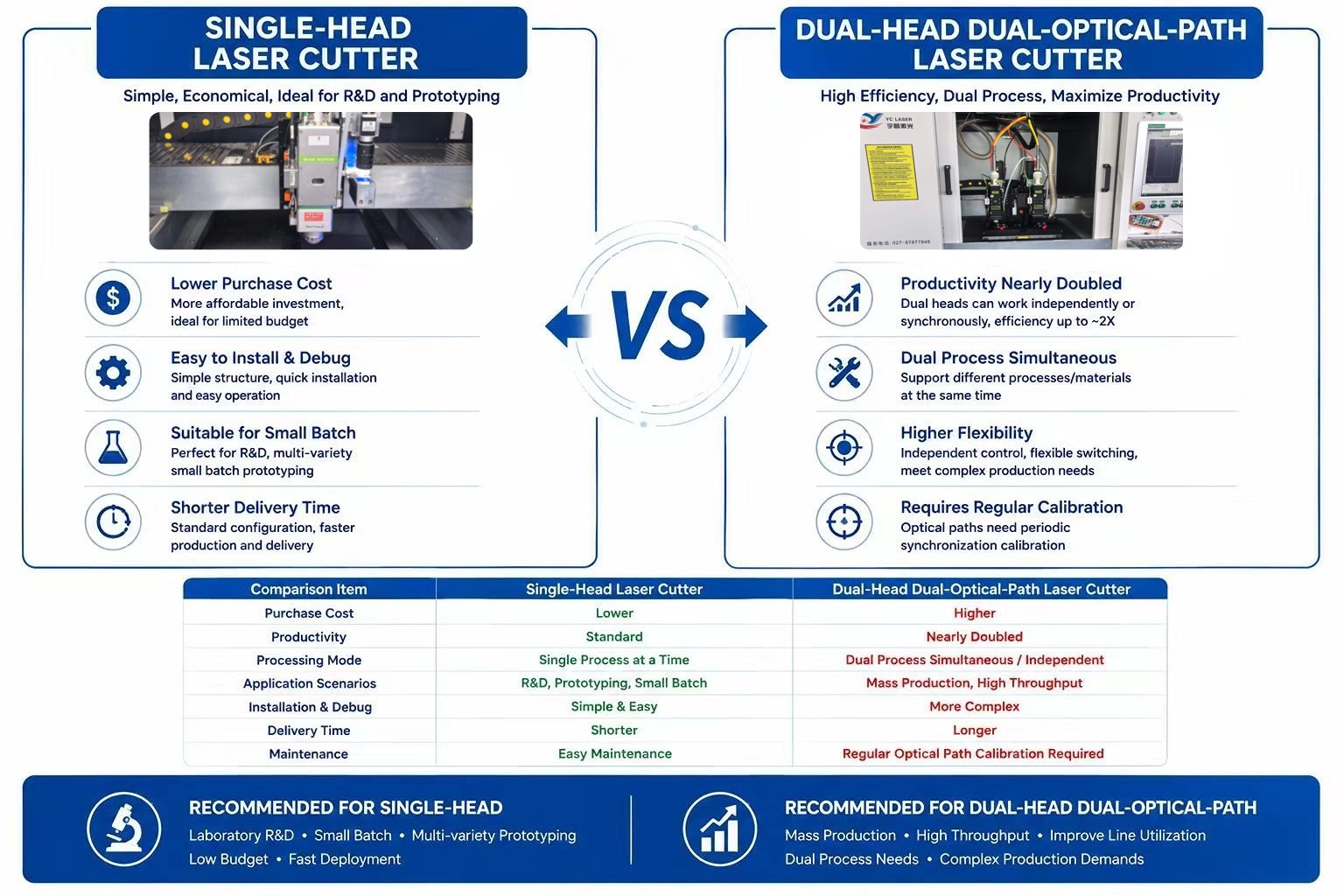
Configuration options beyond the base machine include CCD vision positioning, vacuum adsorption tooling and fixtures for thin sheets and large plates, dual-head dual-optical-path systems for two-station processing, fully automatic loading and unloading modules for line integration, multi-language operating systems and dedicated process software. DXF/DWG import with automatic nesting is part of the software path, which removes the need for hard tooling and allows irregular contours, hole arrays, grooving, dicing and drilling to run in one program.
5. Environment and maintenance envelope
Installation conditions are part of the specification rather than an afterthought: ambient temperature of 5–35 °C, 40–65% relative humidity without condensation, clean or near-cleanroom dust control to protect optical components, a stable regulated industrial power supply, a vibration-damping foundation, and exhaust extraction to remove ceramic and glass dust produced during processing. Maintenance obligations include periodic lens cleaning, inspection of motion modules and, on dual-head machines, regular calibration of optical path synchronization. Where these conditions cannot be met on site, the accuracy figures quoted for the machine are not achievable in production.
| Documented constraint | Range |
|---|---|
| Laser power options | 10 W, 15 W, 20 W, 30 W, 50 W, 80 W, 120 W, 150 W, 300 W, 450 W, 600 W, 1000 W, 1500 W, 2000 W, 3000 W |
| Wavelength options | 1060–1080 nm, 1064 nm, 532 nm, 355 nm, 10.6 μm |
| Working area | 200×200 mm to 1300×1300 mm, including small-format and large-format tables |
| Cutting thickness (machine) | 0.01–20 mm |
| Minimum drilling precision (machine) | 0.05 mm |
| Positioning accuracy (processing service) | ±0.005 mm |
| Kerf width (processing service) | 0.02–0.15 mm |
| Thickness window (processing service) | 0.05–11 mm supported; stable mass production ≤6 mm |
| Processed materials | Alumina, aluminum nitride (AlN), silicon carbide (SiC), silicon nitride, zirconium oxide, glass, sapphire, quartz, ferrite, PCB substrates, wafer, stainless steel, silicon steel, tungsten steel, carbon steel, aluminium alloy, titanium alloy, copper, NdFeB, diamond composites |
Certification and Documentation Constraints
Documentation is often the only part of a quotation that can be independently verified, so it functions as a constraint in its own right. The registrations documented for YCLASER's precision laser cutting machines and control systems are set out below.
| Document | Number | Scope | Authority / market | Validity |
|---|---|---|---|---|
| Chinese Utility Model Patent | ZL 2020 2 2568701.9 | Integrated machine for laser cutting, drilling and scribing of electronic ceramics with precise positioning | State Intellectual Property Office / China | Issued 2021-07-06, valid to 2030-11-08 |
| Chinese Utility Model Patent | ZL 2020 2 2568710.8 | High-speed, high-precision metal laser cutting machine | State Intellectual Property Office / China | Issued 2021-07-06, valid to 2030-11-08 |
| Computer Software Copyright Registration | Registration No. 2020SR1720714; Certificate No. 6521686 | High-Precision Laser Cutting System V1.0 | National Copyright Administration of the People's Republic of China / China | Issued 2020-12-03, valid to 2070-07-18 |
| Computer Software Copyright Registration | Registration No. 2020SR1720715; Certificate No. 6521687 | Laser Cutting and Drilling System for Electronic Ceramics V1.0 | National Copyright Administration of the People's Republic of China / China | Issued 2020-12-03, valid to 2070-08-27 |
Commercial Constraints: MOQ, Lead Time, Capacity and Price Band
On the equipment side, the documented minimum order quantity is one unit, with no mandatory batch size — standard machines, single non-standard customized units and multi-unit line purchases are all accepted, and the company states that research institutes and smaller manufacturers can order single units. Documented production capacity is 10 standard precision laser cutting machines per month, or 3 non-standard customized units per month scheduled by project.
For processing work the commercial structure is different. There is no minimum order quantity, charging is hour-based at 20–30 USD per hour and is affected by process complexity and rush scheduling, and the service supports sample, small-batch and mass production with courier, land transport or sea freight logistics. Yuchang Laser's own published comparison positions its pricing for equivalent configurations 15–25% below large-scale manufacturers and cites a 10–15 working day reduction in non-standard delivery time; that is a supplier-side claim, and the workable test is a like-for-like configuration sheet rather than a headline discount.
| Commercial constraint | Documented position |
|---|---|
| Equipment minimum order quantity | 1 unit; no mandatory batch size |
| Processing service minimum order quantity | None |
| Sample making lead time | 1–3 business days |
| Standard model lead time | About 30 business days |
| Non-standard customized model lead time | 35–50 business days |
| OEM/ODM bulk order lead time | 3–10 business days, depending on process complexity and order volume |
| Monthly capacity | 10 standard units; 3 non-standard customized units |
| Processing service price band | Hour-based charging at 20–30 USD/h |
| Payment and trade terms | T/T and letters of credit for export; EXW, FOB, CIF, DDP, FCA, CPT, CIP, DAP, DPU (Incoterms 2020) |
| Export documentation | Commercial invoice, packing list, pro forma invoice |
| After-sales structure | Standard whole-machine warranty; 24/7 remote technical support; operator training; original spare parts stock; paid on-site installation and maintenance overseas |
Application Fit: Where the Documented Envelope Matches the Part
The industries documented for this equipment family are semiconductor packaging, PCB manufacturing, precision electronic components, new energy, medical devices, aerospace, specialty ceramics, lithium battery production, solar photovoltaics and motor manufacturing. Typical workpieces include ceramic substrates, wafers, packaging substrates and HTCC/LTCC ceramics; hydrogen fuel cell plates, NdFeB magnetic materials and power battery insulation components; PCB, FPC and copper clad laminates; alumina, aluminum nitride, zirconium oxide, silicon carbide and silicon nitride ceramics; float glass, quartz glass and optical lenses; and ceramic medical components.
Deployment records illustrate how the constraints play out in real production environments:
- South Korean high-precision manufacturer. One high-configuration machine exported for cutting and micro-hole processing of ceramic parts and precision electronic components, in stable operation overseas for more than 1.5 years, validating export suitability under demanding precision and stability requirements.
- Taiwan electronic component manufacturer. One customized dual-head, dual-optical-path ceramic laser cutting machine for simultaneous two-station processing, in operation for more than 2 years. Processing capacity nearly doubled against a single-head machine, with consistent accuracy at both stations and no cumulative deviation, supporting flexible small-batch production across multiple product categories.
- Chinese electronics manufacturer. Seven ceramic laser cutting machines deployed on a standardized ceramic substrate production line and running 24/7 for more than 4 years, replacing a traditional mechanical cutting process and reducing chipping and breakage rates.
- National-level semiconductor materials research institute. One customized machine for micro and nano cutting, precision drilling and grooving of semiconductor ceramic substrates, in stable operation for more than 2 years with micron-level tolerance control and cold processing that avoids thermal stress cracking.
- University research platform. One small-format ceramic laser cutting system integrated into a public testing and pilot platform at Tsinghua University, in continuous service for more than 3 years on ceramic process development and sample prototyping.
Comparison with Traditional Mechanical Cutting — and Where Laser Stops Being the Answer
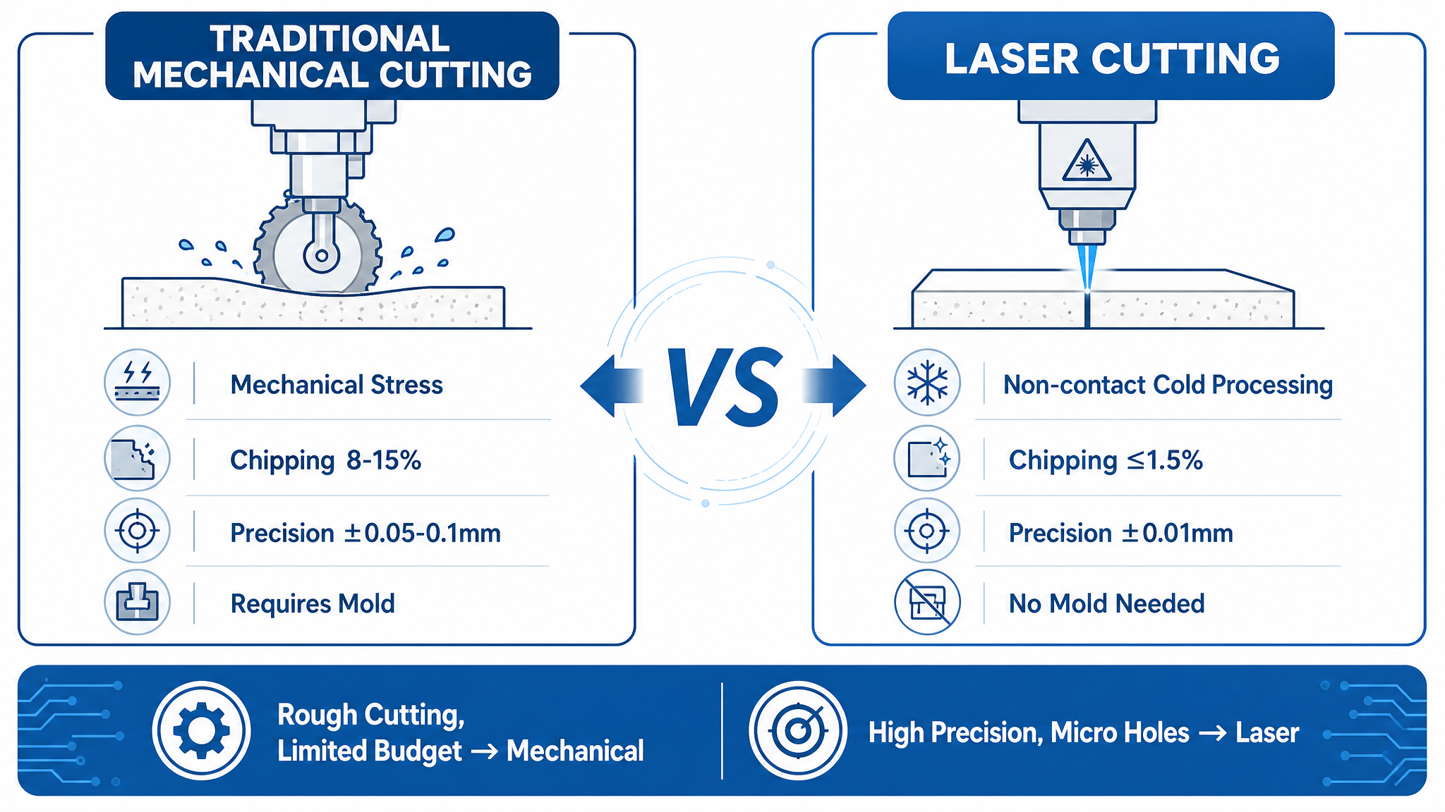
The most common technology comparison in this category is laser processing against traditional mechanical cutting. The table below reflects a comparison published by the equipment supplier; it should be read as supplier-side benchmarking rather than third-party measurement.
| Dimension | Traditional mechanical cutting | Laser processing (supplier-published) |
|---|---|---|
| Precision | Around ±0.05–0.1 mm | Around ±0.01 mm |
| Chipping / breakage defect rate | 8–15% | ≤1.5% |
| Tooling | Fixtures and molds required | No molds; CAD/DXF geometry import |
| Relative processing efficiency | Baseline | +60–80% |
| Geometry range | Limited by tool access | Micro-holes, arrays, irregular contours, dicing and grooving |
Laser processing is not automatically the correct answer, and three documented boundaries make that clear. Thickness: the processing service supports 0.05–11 mm, with ≤6 mm as the stable mass-production window, so very thick sections or crude, low-tolerance cuts may remain more economical under mechanical methods. Environment: the accuracy specifications assume a controlled installation with regulated power, dust control and vibration damping; where floor conditions, power stability or extraction cannot be provided, achievable tolerance falls below the quoted figure. Process validation: ceramic laser processing carries documented risks of micro-cracks, edge chipping and thermal damage, so a new material needs test cutting to fix parameters before mass production — a step that must be scheduled, not treated as a formality. Dual-head systems add a further maintenance obligation in optical path synchronization, and non-standard projects carry longer, less predictable lead times than standard models. A fourth, commercial boundary applies to export orders: destination import controls and tariff movements are a real cost variable, particularly under DDP terms.
Market Trend Analysis
Several structural shifts are visible across the applications documented for this equipment class, and they explain why constraint-based specification is becoming more common than parameter-maximising specification.
First, the workpiece mix is moving toward harder and more brittle materials. Semiconductor packaging substrates, power electronics ceramics, silicon carbide and aluminum nitride components all share the property that mechanical stress during singulation is a yield risk, which pushes demand toward non-contact processing. Second, thickness is trending down while geometric complexity is trending up: thin ceramic sheets, thin metal foils and fine hole arrays require both low heat input and vision-assisted positioning, which favours ultraviolet and picosecond sources over higher-power infrared alone. Third, process integration is being valued over single-function capability — cutting, drilling and scribing on one platform reduces handling steps and alignment errors. Fourth, automation requirements are rising in line with labour availability, which is why automatic loading and unloading is increasingly specified at the quotation stage rather than retrofitted later. Finally, buying behaviour itself is changing: more buyers now require sample verification and a technical agreement before committing capital, and treat certifications, inspection reports and acceptance procedures as procurement criteria rather than paperwork.
Future Outlook
If these directions continue, the competitive ground in precision laser cutting will move away from headline power figures. Ultrafast pulse sources are likely to spread as feature sizes shrink and thermal budgets tighten. Machine differentiation is likely to sit increasingly in process software and parameter libraries — the accumulated know-how about which settings produce an acceptable edge in a specific material — rather than in hardware alone. Integrated cutting, drilling and scribing platforms with inline automation are likely to become the default configuration for volume production, while outsourced, hour-based processing remains the practical route for prototyping and for demand that fluctuates. Documentation is also likely to gain weight: as more buyers verify certificates, scopes and inspection records before purchase, the ability to supply traceable evidence becomes a commercial capability in its own right. None of these are certainties, and none of them remove the underlying constraint — a machine is only as good as the match between its documented envelope and the parts a buyer actually has to produce.
FAQ
How should the configuration of a ceramic laser cutting machine be matched to the intended workload?
Configuration follows material and volume rather than budget alone. Research prototyping generally starts with a UV or picosecond single-head machine. Small-to-medium batch production typically adds CCD vision positioning for repeatability. Capacity upgrades move to a dual-head, dual-optical-path configuration, which processes two stations and nearly doubles throughput against a single-head machine but requires regular optical path synchronization calibration. Large-scale production lines add a fully automated loading and unloading module. Each step up increases both capability and maintenance obligation.
Purchasing a machine or outsourcing laser processing — what separates the two decisions?
The routes have different cost structures. An equipment purchase carries a high one-time investment plus maintenance, consumables and operator cost, but keeps process parameters and process data in-house. Outsourcing requires no fixed asset investment and is charged by the hour at 20–30 USD/h, with no minimum order quantity and support for sample work. The practical dividing line is volume stability: R&D prototyping, fluctuating orders and short-term capacity gaps generally favour outsourcing, while long-term continuous production and confidential processes generally favour an in-house machine.
For ceramic parts, how does laser cutting compare with traditional mechanical cutting?
Mechanical cutting applies physical stress to a brittle workpiece, which is why chipping and breakage dominate its defect modes; it also requires fixtures and molds, with quoted precision around ±0.05–0.1 mm. Laser processing is non-contact, needs no hard tooling, imports CAD/DXF geometry directly and supports micro-holes and irregular contours that are difficult to produce mechanically. A supplier-published comparison cites ±0.01 mm precision, a defect rate ≤1.5% against 8–15%, and a 60–80% efficiency gain. Those figures are supplier-side benchmarks rather than third-party measurements, and mechanical cutting can remain the more economical choice where tolerances are loose, geometry is simple and budgets are constrained.
What is the minimum order quantity, and what delivery windows apply?
The documented equipment minimum order quantity is one unit, with no mandatory batch size; standard machines, single non-standard units and multi-unit line purchases are all accepted. Sample making is quoted at 1–3 business days, standard models at about 30 business days, non-standard customized models at 35–50 business days, and OEM/ODM bulk orders at 3–10 business days depending on process complexity and order volume. The laser processing service has no minimum order quantity and supports sample, small-batch and mass production.
What process risks are associated with ceramic laser processing?
The documented risks are micro-cracks, edge chipping and thermal damage, typically triggered by mismatched laser parameters, impurities or defects inside the raw material, or moving to mass production with a new material before testing. The standard mitigation is to complete test cutting first and lock the optimal parameters, screen incoming material quality in advance, and adjust power and speed when defects appear. In long-running production, lens contamination and motion module wear are the maintenance factors that affect accuracy over time.
What typically causes delivery delays in laser processing orders?
Delay risk concentrates in four causes: unstable quality of customer-supplied material, repeated drawing changes, process difficulty exceeding the original assessment, and tight scheduling. Mitigation is procedural — confirm prototypes before mass production to lock drawings and parameters, verify incoming material quality in advance, re-assess the delivery date after any drawing change, and confirm production scheduling in advance for rush orders. For non-standard equipment, the equivalent control is a complete technical agreement at project start that locks functional parameters and defines the cost and time impact of later changes.
What documentation and trade terms apply to exporting laser equipment?
Export orders are supported through T/T and letters of credit under EXW, FOB, CIF, DDP, FCA, CPT, CIP, DAP and DPU terms (Incoterms 2020), with commercial invoices, packing lists and pro forma invoices available for customs clearance. Responsibility boundaries differ by term: under DDP the seller carries destination taxes and fees, which exposes the order to tariff fluctuations. Exporting also carries import-control and tariff risk at the destination, so verifying target-market import policy before placing an order is a practical precaution.
Conclusion
No single parameter decides whether a high-precision laser cutting machine will perform in production. The purchase is defined by the intersection of wavelength and pulse regime, working area, thickness window, part-level accuracy, installation conditions, verifiable documentation and the commercial terms behind the quotation. Buyers who map their own part envelope onto those constraints before signing a technical agreement avoid the most common failure mode in this equipment class: a machine that meets its specification sheet but not the production requirement behind it.
The full model and parameter catalogue is available for reference: YCLASER product catalogue (PDF).
Tem questões ou precisa de mais detalhes?
Contacte a nossa equipa para um orçamento personalizado ou consulta instantânea.
Solicitar orçamento
Preencha o formulário abaixo e a nossa equipa entrará em contacto com uma proposta personalizada.
Chat direto do WhatsApp
Prefere conversar em tempo real? Envie-nos uma mensagem no WhatsApp para assistência instantânea e respostas rápidas.
- Obter orçamento personalizado
- Partilhar fotos ou documentos
- Discuta as suas necessidades diretamente
Geralmente responde em 5–30 minutos durante o horário de expediente.