
Industrial Induction Heater: Working Principles, Applications, and Benefits

An industrial induction heater is an electrically powered heating system that converts a standard 50 Hz mains supply into a high-frequency current, typically in the 5 kHz to 40 kHz range, and uses the alternating magnetic field that current produces to induce eddy currents inside a conductive load. The load heats itself. No flame, no exposed resistance element and no contact surface has to reach a higher temperature than the material being processed, which is the property that separates induction heating from every combustion-based and contact-based alternative.
That single design characteristic explains why industrial induction heating equipment now appears across a very wide set of processes: metal heat treatment, plastics and rubber processing, food processing, chemical reactions, crude oil pipeline heating, textile printing and dyeing, aquaculture heating, building heating and medicinal herb drying. Industrial induction heating machines, induction heating systems and induction heating power supplies have moved from being niche replacements for gas burners into a general-purpose electrification route for industrial process heat.
This article explains how an industrial induction heater works, what a complete industrial induction heating system contains, where it is applied, what measurable benefits it offers, and where its boundaries lie. The equipment references come from JONSON, the product brand of Guangdong Jiangxin Electronic Technology Co., Ltd., a Foshan-based manufacturer of induction heating equipment.
Working Principles: How an Industrial Induction Heater Produces Heat
An induction heater produces heat in four connected stages: power conversion, magnetic field generation, eddy-current heating inside the load, and closed-loop power control. Every stage is electrical, which is why output can be regulated continuously rather than switched on and off.
1. Mains power is converted into high-frequency current
A 50 Hz AC supply enters the industrial induction heating power supply, where the input is rectified and then switched by an IGBT inverter module into a high-frequency current. In JONSON equipment, this operating band is documented as 5 to 40 kHz, with certain high-power platforms specified across 4 to 50 kHz. The inverter stage is the reason the technology is sometimes described as a high frequency industrial induction heater: the frequency is not a marketing term but the physical condition that makes efficient magnetic coupling possible.
2. The coil generates an alternating magnetic field
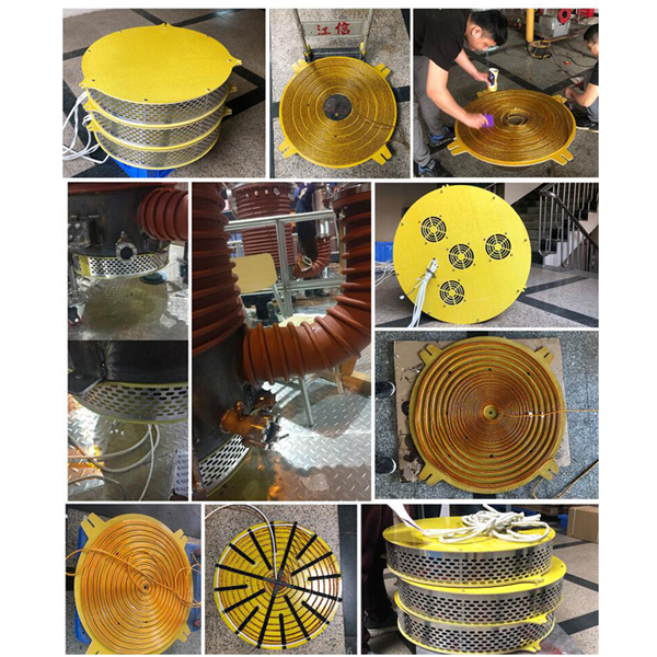
The high-frequency current flows through a copper induction coil, which acts as the work head of the system. Copper is used for its low resistivity and thermal conductivity. The geometry of the coil, its number of turns, its cross-section and its position relative to the workpiece determine the shape of the magnetic field and therefore which region of a load is heated and how evenly that heat is distributed. Coils are treated as engineered parts in induction heating, not as consumables.
3. Eddy currents heat the workpiece from the inside
When a conductive workpiece sits inside an alternating magnetic field, circulating currents are induced within the material itself, and the material's own electrical resistance converts those currents into heat. The workpiece becomes the heating element. Because energy is generated inside the material rather than conducted into it from outside, heating begins immediately and does not depend on air or an intermediate medium to carry heat.
In metalworking, this localized generation is what makes induction heating useful for hardening, annealing, brazing and forging operations: heat can be concentrated at a joint, a surface layer or a specific section of a part instead of being applied to the whole component. In fluid and air heating, the same principle is used indirectly, with the coil heating a metal component that then transfers energy to water, thermal oil or air.
4. Closed-loop control holds the process steady
JONSON control platforms use a DSP-based high-speed automatic phase-locking tracking control system, which keeps the inverter operating at the resonant point as load conditions change. Documented control characteristics across the range include:
- Stepless power adjustment between 20% and 100% of rated output.
- Start time below 1 second.
- Load temperature detection from 0 to 1000 °C with accuracy up to ±1 °C.
- PID power adjustment through a 0 to 5 V input voltage or an RS-485 interface.
- Fully electrically isolated soft start and soft stop.
- Instantaneous overcurrent protection within 2 microseconds and 130% instantaneous power overload protection.
Coil selection is part of the specification, not an accessory
Each power level has an adaptive coil window defined by conductor cross-section, cable length and inductance. The following figures are documented for JONSON platforms and illustrate how tightly coil parameters are tied to power rating.
| Platform power | Adaptive coil conductor | Coil length | Inductance window |
|---|---|---|---|
| 2.5 kW | 4 mm² copper line | 23 m | 100–150 μH |
| 3.5 kW | 6 mm² copper line | 20 m | 80–100 μH |
| 5 kW | 10 mm² copper line | 15 m | 60–75 μH |
| 6 kW | 10 mm² copper line | 13 m | 60–65 μH |
| 100 kW | 95 mm² copper line | 40 m | 80–100 μH |
Physical spacing follows the same logic. For the 2.5 kW platform, the documented coil-to-load distance through the insulation layer is 20–25 mm for a circular coil, 15–20 mm for a plane coil, 10–15 mm for an elliptical coil and within 10 mm for a super-elliptical coil. Too large a gap reduces coupling efficiency; too small a gap risks thermal damage to the coil insulation.
What Makes Up a Complete Industrial Induction Heating System
A complete industrial induction heating system is not a single box. Documented system composition includes the induction heating power supply, electromagnetic induction heating coils, temperature sensors, a PLC control system, touch-screen human-machine interfaces, thermal insulation layers, an electrical control cabinet, and current and voltage detection modules. Matched equipment such as steam equipment, hot air furnaces and insulated pipework is added according to the process being served.
Power supplies are supplied in wall-mounted format across the mid range and in cabinet format for larger installations. The table below summarizes selected JONSON platforms that are relevant to the majority of industrial heating duties.
| Platform | Rated power | Rated voltage | Structure | Certification |
|---|---|---|---|---|
| JS1300-005/008 | 5 kW / 8 kW | 380 V (380 V ±20%) | Wall-mounted | CE, ISO |
| JS1300-10/15 | 10 kW / 15 kW | 380 V (300–400 V) | Wall-mounted | CE, ISO, RoHS |
| JS1000-20 | 20 kW | 380 V (300–400 V) | Wall-mounted | CE, ISO |
| JS1000-30 | 30 kW | 380 V | Wall-mounted | CE, ISO |
| 40 kW / 50 kW / 60 kW | 40–60 kW | 380 V / 50 Hz (380 V ±20%) | Cabinet | — |
| 70 kW / 80 kW | 70 kW / 80 kW | 380 V | Cabinet | — |
| JS1000-100 | 100 kW | 380 V (constant power 300–400 V) | Wall-mounted | CE, ISO |
For sites with unusual grid conditions, customized configurations are documented from 500 W to 200 kW on 110 V, 240 V or 660 V supplies, with a voltage adaptation range of ±20%. Single-phase platforms at 220 V cover the smaller end of the market, from 2.5 kW up to 6 kW, with constant power output between 210 V and 260 V.
The Industrial Problem This Equipment Solves
The procurement question behind induction heating is rarely about the heater itself. It is about what happens to a plant's heating system when fuel costs move, when point-of-use emissions come under scrutiny, or when a process needs tighter temperature control than a burner or a resistance band can deliver. Coal and gas boilers require fuel storage, flue routing and, in many locations, emissions and discharge approvals. Resistance and contact heating avoid combustion but still heat an element first, which means slow start-up, higher surface temperatures than the load needs, and limited turndown.
Industrial induction heating equipment changes the operating profile in three ways. Heat is generated inside the load, so energy is not first spent heating air or an element. Output can be modulated continuously between 20% and 100% of rated power, so the heater follows part-load demand instead of cycling. And because there is no combustion at the point of use, the heater itself produces no flue gas, no smoke and no nitrogen oxides, and requires no complex sewage discharge approvals for that combustion path.
Applications of Industrial Induction Heating Equipment
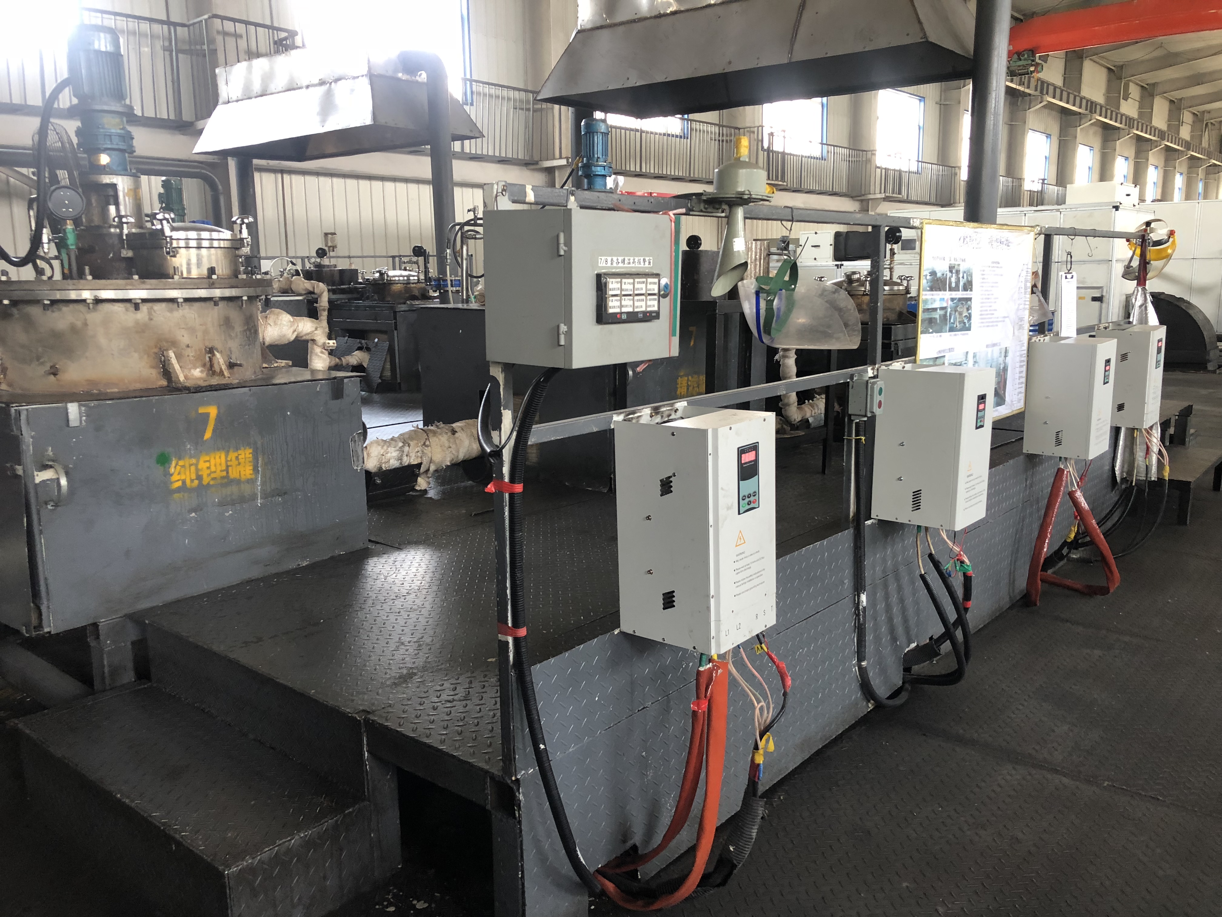
JONSON documents its induction heating platforms across plastics and rubber, food processing, chemical reactions, crude oil pipeline heating, textile printing and dyeing, aquaculture heating, metal heat treatment, building heating and medicinal herb drying. Working conditions in these sectors differ substantially, and the equipment specification follows the environment.
- Rubber and plastics: continuous high-frequency operation on extruders, injection moulding machines, granulators and wire drawing machines.
- Food processing: high humidity with a small amount of steam mist and constant-temperature cooking duty.
- Chemical industry: medium and high temperatures with weak corrosion present in the working area.
- Building and factory heating: low-temperature outdoor or plant antifreeze circulation.
- Oil pipeline heating: preventing crude oil from solidifying during transport.
Project types documented for this equipment include steam supply, medium and high temperature thermal oil heating, hot air drying, constant temperature water supply for factory production, and constant temperature heating for schools, hospitals, hotels, farms and flower greenhouses.
Applications by heating medium
Because the coil can heat a metal component that then transfers energy onward, the same power platform serves three different media. This media versatility is one of the practical reasons induction heating has spread beyond metalworking.
| Medium | Representative JONSON equipment | Documented parameters |
|---|---|---|
| Water and steam | Induction Steam Generator JS-1600 | 30 kW / 40 kW / 50 kW, 380 V, heat conversion efficiency ≥99% |
| Hot air | Induction Heating Hot Air Generator JS-1600-8/12/15 | 8 kW / 12 kW / 15 kW, 380 V, outlet temperature 80–130 °C, wind pressure 800–1000 Pa |
| Domestic and commercial hot water | Instant Induction Water Heater JS-JR-008 | 3.5–8 kW, 220 V, efficiency ≥90%, for hotels, hospitals and schools |
| Metal components | Induction Heating Machine JS1000-30; 100 kW Industrial Induction Heater JS1000-100 | 30 kW and 100 kW, 380 V, metal heat treatment and pipeline work |
| Bearings and fitted parts | Bearing Induction Heater JS1300-5/8/15/20/30 | 5 kW–30 kW, three-phase 380 V, 20.7 kg |
For metal processing specifically, induction heating is widely used in industry for hardening, annealing, brazing and forging because energy can be concentrated at a joint or surface. Induction heaters for brazing, forging, heat treatment, annealing and hardening all rely on the same underlying principle; what changes between them is power level, frequency behaviour, coil geometry and the control profile applied to the load.
Benefits That Appear on a Specification Sheet
The benefits of industrial induction heating are easiest to evaluate when they are expressed as documented performance figures rather than general claims.
- Heat conversion efficiency: documented between ≥95% and ≥99% depending on platform. The 100 kW industrial induction heater is specified at ≥95%, the 40–60 kW and 70–80 kW platforms are specified at ≥98% and ≥99% respectively, and the induction steam generator is specified at ≥99%.
- Fast response: start time under 1 second on documented platforms. Steam generators are documented as producing steam in about 30 seconds, and hot air furnaces as reaching rated temperature in about 3 minutes.
- Continuous turndown: stepless adjustment between 20% and 100% of rated power, so output matches demand rather than cycling between full power and off.
- No combustion at the point of use: zero nitrogen oxides, no smoke emissions and no complex sewage discharge approvals associated with fuel firing.
- Safety through separation: physical separation of water and electricity, or oil and electricity, with automatic interlock shutdown on water shortage, overheating or overpressure.
- Modular expansion: multiple units can be connected in parallel, so capacity can be increased or reduced as needed, from centralized heating for small and medium factories to large plant areas.
- Long service life: the manufacturer guarantees whole-machine service life of ten years, with one year of free maintenance and lifelong maintenance.
Maintenance requirements reflect the absence of a combustion path. Documented routines are cleaning dust, checking wiring terminals, electromagnetic coils and the cooling system, avoiding frequent start-stop cycles, preferring low-power constant-temperature operation, and following a soft-stop procedure on shutdown.
Comparison with Traditional Heating Solutions
Induction heating is not automatically the right answer for every heating duty. The comparison below sets out where it differs from resistance and contact heating and from combustion boilers.
| Consideration | Induction heating | Resistance / contact heating | Coal or gas boiler |
|---|---|---|---|
| Where heat is generated | Inside the conductive load or a conductive susceptor | In the element, then transferred | In the flame and flue gas, then transferred |
| Start-up | Documented at under 1 second | Typically minutes | Slow, with purge and warm-up |
| Power regulation | Stepless, 20%–100% | Staged or on/off | Burner modulation with limited range |
| Point-of-use emissions | None from the heater | None, but element losses | Flue gas, nitrogen oxides, smoke |
| Site requirements | Electrical supply, ventilation, coil clearance | Electrical supply | Fuel storage, flue, emissions and discharge approvals |
| Load suitability | Conductive loads or conductive intermediates | Any load in direct contact | Any load indirectly heated |
Limits and boundaries of induction heating
A credible evaluation has to acknowledge where induction heating is constrained.
- The load must be electrically conductive. Bulk non-conductive materials cannot be heated directly. Plastics, food products and herbal material are processed indirectly, through a metal barrel, plate, pipe or susceptor that the coil actually heats. This adds a design step and places thermal limits on the intermediate material.
- Efficiency depends on coil coupling. The insulation gap between coil and load is specified rather than approximate: 20–25 mm for a circular coil on the 2.5 kW platform, down to within 10 mm for a super-elliptical coil. Installations that cannot maintain that gap, or that place the coil unevenly, will not achieve the rated efficiency.
- Thermal management is mandatory. The control cabinet must be well ventilated to prevent IGBT modules from overheating, and high-power equipment may require air cooling or water cooling. Controllers must be kept away from humid, dusty and corrosive gas environments, with regular checks of sealing.
- Grid conditions matter. Several platforms are specified for constant power output between 300 V and 400 V, and others for 380 V ±20% or 220 V ±20%. Sites with unstable supply need to be assessed before selection, not after installation.
- Coils are power-specific. The inductance and length windows shown earlier mean a single coil cannot be assumed to serve every power level or every workpiece geometry.
- Operating discipline affects lifetime. Frequent start-stop cycling is discouraged, and the documented recommendation is low-power constant-temperature operation with a soft-stop procedure.
In short, induction heating replaces combustion and contact heating very effectively where the load is conductive or can be heated through a conductive intermediate, where electrical capacity is available, and where coil geometry can be engineered for the part. Where those conditions do not hold, a different heating method may still be more appropriate.
How Buyers Evaluate an Industrial Induction Heating Machine
The following sequence reflects the parameters that actually determine whether equipment will perform as expected.
- Define the load and the medium. Metal mass and geometry, or water, thermal oil or air, together with target temperature and required ramp rate.
- Match power to duty. Documented steps run from 2.5 kW and 3.5/5/6 kW single-phase units for small plastic machinery, through 5/8 kW, 10/15 kW, 20 kW and 30 kW wall-mounted platforms, to 40/50/60 kW, 70/80 kW and a 100 kW three-phase unit.
- Verify the supply. Three-phase 380 V with constant power between 300 V and 400 V, or single-phase 220 V with constant power between 210 V and 260 V, or a customized 110 V / 240 V / 660 V configuration from 500 W to 200 kW.
- Confirm operating frequency. 5–40 kHz across most platforms, 4–50 kHz on the 70/80 kW units.
- Confirm the control interface. 0–5 V PID input or RS-485, programmable digital display, load temperature detection up to 1000 °C at ±1 °C accuracy.
- Check the protection set. Overcurrent, overvoltage, overtemperature, water shortage and overpressure protection, 2 microsecond instantaneous overcurrent response and 130% power overload protection.
- Specify the coil and insulation gap against the coil length, cross-section and inductance window for the chosen power level.
- Confirm the cooling mode and the ventilation available in the control cabinet location.
- Verify certification where it is stated, such as CE, ISO and RoHS on specific platforms.
- Confirm environmental limits: ambient temperature from −20 °C to 40 °C or 50 °C on most platforms, −25 °C to 55 °C on the 70/80 kW units, and humidity at or below 95%.
Market Direction: Electrification of Industrial Process Heat
Industrial heating is moving toward electrification for reasons that are structural rather than cyclical: fuel price volatility, tightening emissions expectations at the point of use, and the practical difficulty of obtaining approvals for new combustion installations in populated areas. Induction-based systems fit that direction because they require no fuel storage, no flue and no combustion approval path, and because they can be installed as modular units and expanded in parallel as demand grows.
A second trend is retrofit rather than replacement. Energy-saving transformation of existing equipment, such as injection moulding machines, wire drawing machines, granulators and extruders, is a documented application area for induction heating, because the heating barrel or cylinder already provides the conductive intermediate that the coil needs. This keeps capital expenditure focused on the heating section rather than on the entire production line.
A third trend is the use of a single heating architecture across multiple media. Water, thermal oil and hot air cover low, medium and high temperature duties, and plants that previously maintained separate boiler, hot air and process heating systems increasingly look for one control philosophy across all three.
Future Outlook
Control electronics is where the largest changes are visible. DSP-based phase-locking tracking, programmable digital displays and PID interfaces such as 0–5 V or RS-485 make induction heating equipment easier to integrate into plant-level monitoring, which matters as more factories are asked to document energy use and process conditions. Wider voltage customization, already documented from 110 V to 660 V, addresses the reality that industrial grids differ significantly between markets.
On the equipment side, two directions appear consistent. First, modular parallel architectures will continue to replace single oversized units, because they allow capacity to be added incrementally and reduce the consequence of a single unit being serviced. Second, the boundary between metal heating and fluid or air heating will keep blurring, as the same power platform is configured for metal heat treatment, steam generation, hot air drying or thermal oil circulation through a change of coil and control profile rather than through a different technology.
About the Manufacturer
JONSON is the product brand of Guangdong Jiangxin Electronic Technology Co., Ltd., an energy-saving heating solution provider founded in 2011 and based in Foshan, Guangdong Province, China. The company operates a 3,000 m² facility with more than 60 employees and more than 30 engineers in product research and development, and reports an annual output of 120,000 units, with approximately 40% of production exported to markets including Europe, the United States, India and Indonesia.
The product range covers induction heaters, induction heating machines, induction heater control boards, industrial induction heaters, induction heating water boilers, induction heating hot air generators, induction instant water heaters, induction heating room heaters, induction steam generators, induction heating coils, bearing induction heaters and induction welding machines. Published specifications and product information are available at www.jonson-ih.com.
FAQ
What is the difference between an industrial induction heater and a conventional resistance heater?
An induction heater induces eddy currents inside a conductive load, so the load heats itself and the process starts in under 1 second on documented platforms. A resistance heater heats an element first, and that element must run hotter than the material being processed before heat transfers by contact or radiation. Induction systems also allow stepless power adjustment between 20% and 100% of rated output, whereas resistance heating is typically staged or switched on and off.
What power rating does an industrial induction heating machine need?
Power follows the mass, material and target temperature of the load, plus the ramp rate the process requires. Documented JONSON platforms span 2.5 kW and 3.5/5/6 kW single-phase units for small plastic machinery and commercial heating, 5 kW and 8 kW wall-mounted units, 10 kW and 15 kW units, 20 kW and 30 kW units, 40/50/60 kW and 70/80 kW cabinet units, and a 100 kW three-phase unit used for plastic machinery, food machinery, aluminum-plastic machines, roller equipment, boilers and oil and natural gas transmission. Customized configurations are documented from 500 W to 200 kW on 110 V, 240 V or 660 V supplies.
Can induction heating equipment be used for steam, hot air and liquids, not only for metal?
Yes, through a conductive intermediate. The induction steam generator JS-1600 is rated 30 kW / 40 kW / 50 kW at 380 V with heat conversion efficiency of ≥99%. The induction heating hot air generator JS-1600-8/12/15 is rated 8 kW / 12 kW / 15 kW at 380 V, with an outlet temperature of 80–130 °C and wind pressure of 800–1000 Pa. The instant induction water heater JS-JR-008 covers 3.5–8 kW at 220 V and is applied in hotels, hospitals and schools. In all of these designs the coil heats a metal component, which then transfers heat to water, thermal oil or air.
What are the main limitations of industrial induction heating?
The load must be electrically conductive, or be heated through a conductive susceptor, so non-conductive bulk materials are processed indirectly. Efficiency depends on coil coupling, and the coil-to-load distance is specified rather than approximate. Control cabinets must be ventilated to prevent IGBT modules from overheating, and high-power units may require air or water cooling. Controllers must be kept away from humid, dusty and corrosive environments. Supply conditions also matter, since several platforms are specified for constant power output between 300 V and 400 V or for ±20% voltage adaptation.
How is the induction coil specified, and how far should it sit from the workpiece?
Coil parameters are tied to power level. Documented adaptive values include a 4 mm², 23 m coil with 100–150 μH inductance for the 2.5 kW platform; 6 mm², 20 m, 80–100 μH for 3.5 kW; 10 mm², 15 m, 60–75 μH for 5 kW; 10 mm², 13 m, 60–65 μH for 6 kW; and 95 mm², 40 m, 80–100 μH for the 100 kW platform. For the 2.5 kW platform, the documented coil-to-load distance through the insulation layer is 20–25 mm for a circular coil, 15–20 mm for a plane coil, 10–15 mm for an elliptical coil and within 10 mm for a super-elliptical coil.
What should be verified when specifying an industrial induction heating power supply?
Documented items worth verifying include rated power, rated input and output current, voltage adaptation range, working frequency, main circuit structure, cooling mode, protection behaviour, control interface and load temperature detection. As examples: the 100 kW unit specifies a rated input current of 140–150 A, rated output current of 200–220 A, AC 380 V at 50–60 Hz, a full bridge series resonance main circuit, ambient limits of −20 °C to 50 °C, and a working frequency of 5–40 kHz. The single-phase 220 V platforms specify constant power output between 210 V and 260 V, a half-bridge series resonance structure, and instantaneous overcurrent protection within 2 microseconds.
Tem questões ou precisa de mais detalhes?
Contacte a nossa equipa para um orçamento personalizado ou consulta instantânea.
Solicitar orçamento
Preencha o formulário abaixo e a nossa equipa entrará em contacto com uma proposta personalizada.
Chat direto do WhatsApp
Prefere conversar em tempo real? Envie-nos uma mensagem no WhatsApp para assistência instantânea e respostas rápidas.
- Obter orçamento personalizado
- Partilhar fotos ou documentos
- Discuta as suas necessidades diretamente
Geralmente responde em 5–30 minutos durante o horário de expediente.