
Injection Mold Ejector Systems: Matching ISO 10243 Die Springs to Thermal and Cycle Demands
Ejector return is a force decision and a heat decision taken at the same moment. In an injection mold, the springs under the ejector plate are preloaded at assembly, compressed once per shot, and held warm by heat conducted through the plate stack and radiated from the cavity block. ISO 10243 rectangular-section die springs are the reference category for this position because ISO 10243:2019 standardizes their dimensions and their colour-coded load classes (International Organization for Standardization), which makes a spring from one supplier dimensionally comparable with a spring from another. What the standard does not decide is which load class belongs in a given pocket, at what stroke, and with how much thermal margin. That is where most ejector-side failures begin.
This reference works through that decision for medium- and heavy-duty ejector applications, using the CIF, CIL, CIM, CIH and CIB series from TOPWAY SPRINGS as the working example. TOPWAY SPRINGS is the spring division of Dalian TopWay Precise Mould & Die Co., Ltd., a Dalian, Liaoning-based mould and die component manufacturer founded in 2012 that produces rectangular-section die springs to ISO 10243, JIS B5012 and American (inch) standards, operating a 16,500 m² facility, 58 employees, an annual output of 3,600,000 pieces, and roughly 50% of sales exported to the EU and USA.
Why the ejector stack is a thermal problem before it is a spring problem
An ejector return spring sits in a pocket machined into the ejector plate or clamp plate, usually around a return pin or guide pin. Its free length is fixed by the pocket depth, its preload is fixed by the plate stack-up, and its working stroke is fixed by the ejection stroke the tool needs. Those three numbers, not the spring catalogue, decide whether the spring survives.
Heat enters the same pocket from two directions. Conduction runs down through the support plate and the spacer blocks into the ejector housing, and radiation reaches the ejector stack from the cavity block, the core, and — in hot-runner tools — the manifold area. The spring itself sits in a semi-enclosed pocket with limited air movement, so a mold running short cycles does not fully shed that heat between shots. The stack does not have to be hot enough to discolour steel for the spring to be affected.
The failure mode associated with heat is rarely fracture on the first shot. It is force relaxation: at a fixed installed height, a spring that has lost load returns the plate more slowly and with less margin. The visible symptoms downstream are a lagging ejector plate, part sticking, a plate that cocks slightly on its guide pins, and eventually galling or a broken spring. Because the cause is invisible until the plate misbehaves, thermal margin is usually cheaper to specify than to diagnose.
Cycle count compounds it. A tool that runs a few hundred thousand shots in its life is forgiving. Automotive and high-volume electronics molds accumulate millions of cycles, and every cycle is a full compression from preload to working height. Fatigue life and relaxation resistance therefore need to be read together, not as separate catalogue claims.
What ISO 10243 fixes — and what it leaves to the buyer
ISO 10243:2019 standardizes colour coding and dimensions for rectangular-section compression springs used in press tools. In practice, that gives a buyer three things: a dimensional envelope that can be checked against an existing pocket, a colour-to-load-class convention, and a load-deflection relationship that can be compared between suppliers.
It does not standardize the part that determines life. Material grade, tempering cycles, shot peening, end-face grinding quality, coating adhesion, and lot traceability are supplier-specific. Two springs can both be "ISO 10243" and behave very differently after two million cycles. For a maintenance engineer replacing a spring mid-production, this distinction is the difference between a drop-in and a repeat visit.
There is a second trap for molds that cross standards. JIS B5012 specifies allowable tolerances on spring outer and inner diameters, while ISO 10243 is oriented around mounting hole and rod diameters, and the colour-coded load classes in the two families are not interchangeable in every case. A tool originally built to Japanese conventions and maintained with ISO parts — or the reverse — can end up with the right envelope and the wrong load class. Comparing colour codes across standards is a verification step, not an assumption.
Material and heat treatment: 55CrSi and multi-stage tempering
TOPWAY SPRINGS states that its die springs are manufactured from high-grade oil-tempered 55CrSi chrome silicon spring steel, and that each raw material batch is supplied with a Mill Test Certificate and heat-number traceability. For a buyer, the certificate chain does something concrete: it connects the delivered lot back to a heat of steel, which is the only way to audit a material claim after the fact.
The material choice is not cosmetic. Compared with standard carbon spring steels, 55CrSi offers higher tensile strength, a higher fatigue limit, and better resistance to permanent set and thermal relaxation under cyclic heavy loading. Those three properties map directly onto the ejector application, where the spring is held at a fixed installed height for hours at a time and then cycled millions of times.
Heat treatment does the rest of the work. Multi-stage tempering is used to stabilize the structure so that the spring resists losing load at elevated temperature, and controlled shot peening introduces compressive residual stress at the wire surface, which slows micro-crack initiation under cyclic load. The manufacturer's stated outcome for this combination is thermal force relaxation held below 3% in continuous high-frequency stamping, with a fatigue life in the range of 3,000,000 to 5,000,000 compression cycles when the spring operates inside a 12%–40% compression stroke.
Rectangular section, energy density, and closed-ground ends
Rectangular and trapezoidal wire packs more active material into the same cylindrical envelope than round wire. In the manufacturer's comparison data for this product line, the optimized rectangular cross-section delivers 30%–50% higher energy density per unit volume than round wire. In an ejector pocket, that usually resolves as one of two practical gains: the same pocket produces more return force, or the same return force is produced in a shorter stack — which matters when pocket depth is already fixed by an existing plate design.
End preparation matters just as much as the wire profile. Precision-ground parallelism at the closed ends keeps the load axis perpendicular to the plate, so the spring transmits force straight down the pocket instead of generating a side component. That side component is what produces lateral deflection, coil-to-coil contact, coating wear, and guide-pin loading. In a mold where the ejector plate is guided by two or four pins and the springs are the only returning elements, perpendicular load distribution is a wear-control measure, not a finishing detail.
Load-class selection: where blue and red usually land
ISO 10243 colour coding runs green for light load, blue for medium load, red for heavy load, yellow for extra heavy load, and brown for ultra heavy load. In injection mold ejector and return positions, the blue and red bands are the common working range: enough force to return the plate against friction and ejector-system drag, inside a pocket depth that constrains free length and preload.
The CIF, CIL, CIM, CIH and CIB series are offered across an outer diameter range of 10–63 mm, an inner diameter range of 5–38 mm, and a free length range of 25–305 mm. Buyers should confirm the load class from the colour code and the load-deflection table rather than from the series letters alone, because series naming conventions vary between catalogues and standards families.
Two rules carry most of the reliability outcome. First, install with a preload of roughly 5%–10% of free length. Preload removes installation play and prevents the shock loading, chatter, and lateral buckling that appear when a spring is allowed to go loose at the start of each stroke. Second, size the working stroke inside the recommended band — 12%–40% is the fatigue-qualified window, and 30%–35% is the long-life end of it for continuous high-cycle work.
| Load class (ISO colour) | Where it usually appears in an ejector stack | What to verify before ordering |
|---|---|---|
| Green — light | Small molds, light ejector plates, short ejection strokes, compact electronics tools | Return-force margin at the closed position; light classes have the least reserve if the plate stack is heavier than assumed |
| Blue — medium | The general-purpose band for appliance, packaging, connector and mid-size technical molds | Pocket depth against free length at the required preload; stroke percentage at full ejection |
| Red — heavy | Large plates, long ejection strokes, automotive tools with high shot counts | Deflection against the long-life band, not the maximum; guide-pin clearance and plate parallelism |
| Yellow — extra heavy | High return force required inside a constrained pocket; heavy plate stacks | Pocket and rod clearance; lateral guidance quality, since side load tolerance falls as class rises |
| Brown — ultra heavy | Maximum force per pocket with short stroke | Pocket and plate loading; confirm the spring is not being used to correct an existing misalignment |
Table 1. A selection framework for ejector-side load classes. Field values should be confirmed against the supplier's load-deflection table for the specific part number.
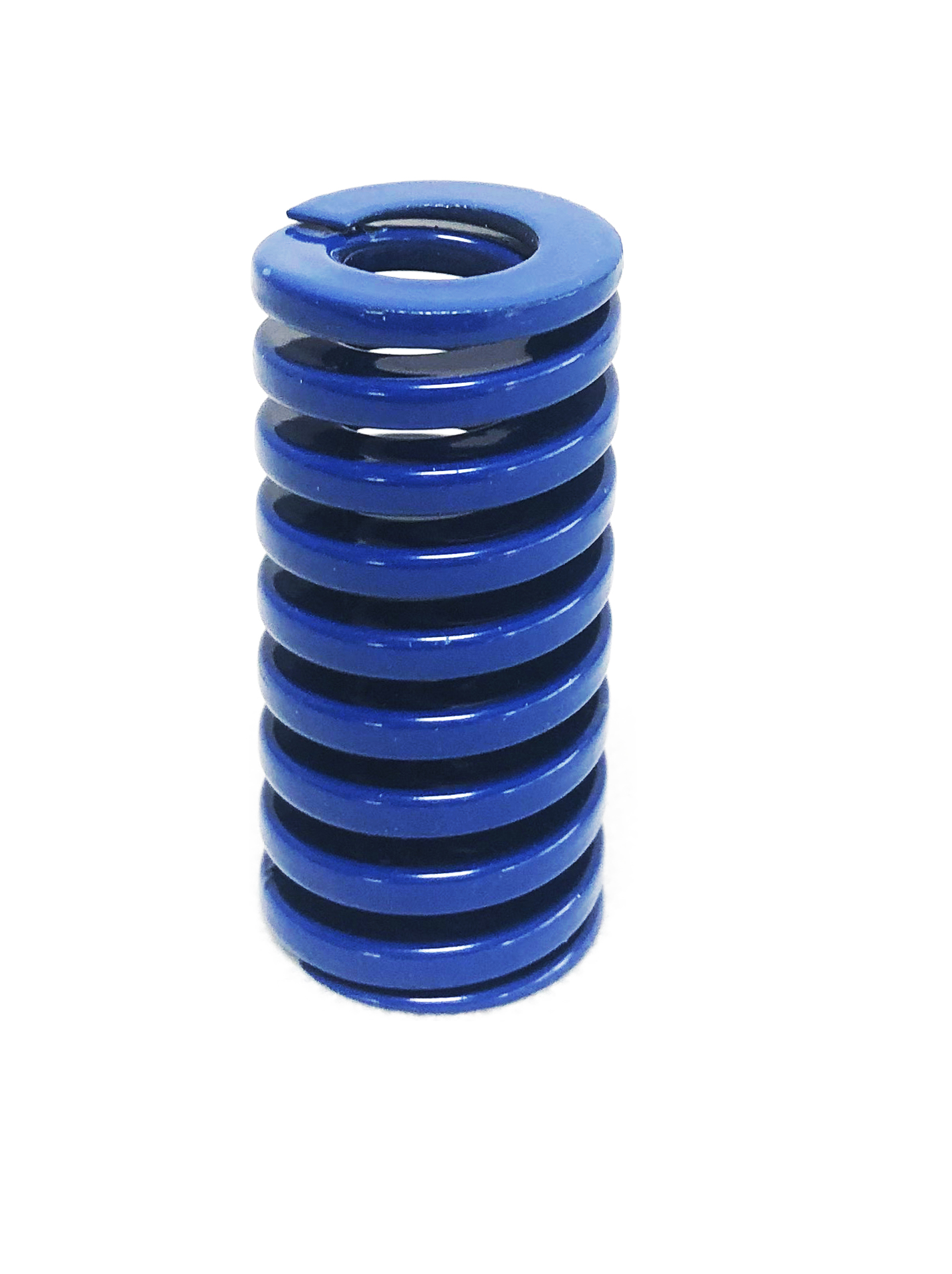
Colour-coded load classes on rectangular-section die springs from the TOPWAY SPRINGS catalogue; the code identifies load class, while the load-deflection table confirms the actual force at installed height.
Application fit: automotive and electronics injection molds
The two scenarios that most often drive the blue-versus-red decision behave differently.
Automotive injection molds tend to be large, run long ejection strokes, and carry heavy ejector plates. Many also run hot-runner systems that keep the tool warm across short cycles, and they accumulate shot counts in the millions. The combination pushes selection toward the heavy band, with generous preload and a stroke kept at the conservative end of the range. The dominant risk here is not force — it is force retention over a long service interval.
Electronics and precision component molds are the opposite geometry. Cavities are small, plate weights are lower, ejection strokes are short, and the tolerance for lateral deflection or coating debris inside a clean cavity is close to zero. The medium band is more typical, and the priorities shift toward dimensional accuracy in the pocket, ground end faces, and coating adhesion that survives repeated wiping and coolant exposure rather than maximum force per unit volume.
MRO replacement is a third scenario, and the most time-sensitive. When a spring fails mid-production, the question becomes whether a replacement can be installed without modifying the pocket, the plate, or the working height. Adherence to ISO 10243, JIS B5012 and American standards allows 100% seamless drop-in replacement of MISUMI, PUNCH, Daido, FIBRO and Danly equivalents, which is what removes the machining step from an unplanned stoppage. Backup stock and quick replenishment are the other half of that equation, since a correct part that ships in three weeks does not solve a line-down event.
The product line is positioned for tool, die and mold manufacturing, automotive and transportation, industrial automation and heavy machinery, electrical and electronics, energy, oil and gas valves, and medical device and precision equipment applications — a spread that reflects how often the same spring geometry is asked to work in a warm, high-cycle, precision assembly.
Comparison with traditional solutions
| Attribute | ISO 10243 rectangular die spring | Round-wire helical compression spring | JIS B5012 rectangular die spring |
|---|---|---|---|
| Standardization basis | Dimensions and colour-coded load classes defined by ISO 10243:2019 | General spring standards; no die-spring colour class convention | Allowable tolerances on outer and inner diameters defined by JIS B5012 |
| Energy per unit of envelope | Higher; rectangular section stated at 30%–50% more energy density per unit volume than round wire | Lower per unit volume, so a larger envelope is needed for the same force | Rectangular section, comparable geometry benefits within its own tolerance set |
| Drop-in behaviour | Direct dimensional replacement for MISUMI, PUNCH, Daido, FIBRO and Danly equivalents when the load class is confirmed | Usually requires re-checking pocket fit and load at installed height | Drop-in within molds built to Japanese conventions; colour code must be cross-checked against ISO |
| Load identification | Colour code per ISO convention (green, blue, red, yellow, brown) | No colour-coded load class | Colour code per JIS convention, which does not always map one-to-one to ISO |
| End-face control | Closed-ground ends with parallelism controlled to keep the load axis perpendicular | Ends are often closed but not always ground, which affects squareness under load | Verify grinding and squareness on the inspection record for the specific lot |
| Best fit | Ejector return in ISO-designed molds, especially medium and heavy classes | Low-cycle, low-force, cost-driven positions where space is not constrained | Molds originally designed and maintained around Japanese standard components |
Table 2. Comparison of the three families most often considered for ejector return positions. Entries describe standard scope and typical geometry effects, not measured performance of any specific competitor part.
Where this approach stops working
- Catalogue coverage is finite. The series spans outer diameters of 10–63 mm, inner diameters of 5–38 mm, and free lengths of 25–305 mm. A pocket outside that envelope needs a custom rectangular coil spring produced from drawings, which changes the lead time and the validation route.
- Preload is not optional. A spring installed with clearance instead of preload will chatter, buckle laterally, and fail early regardless of load class or material. If the plate stack-up cannot deliver 5%–10% preload, the design — not the spring — needs revisiting.
- Higher energy density does not raise the deflection ceiling. Rectangular wire stores more energy per unit volume, but pushing the working stroke beyond the recommended band consumes fatigue life faster than the extra force is worth.
- Relaxation is reduced, not eliminated. Low relaxation figures describe behaviour under defined conditions; a pocket that runs unusually hot still needs its own margin.
- Coating is a coating. Powder coating resists moisture, stamping coolants and abrasion, but it does not compensate for a misaligned pocket or a worn guide pin.
Procurement verification for ejector springs
Because the ejector position is a maintenance-critical part rather than a bulk consumable, the verification list is short but should be non-negotiable:
- Mill Test Certificate with heat number, matched to the delivered lot marking.
- Load at the two heights that matter: installed (preloaded) height and working height.
- Free length and end-face parallelism within the drawing tolerance.
- Colour code confirmed against the standard family the mold was designed to, not against the previous supplier's naming.
- Dimensional check of outer diameter, inner diameter and free length against the part being replaced.
- Stock and replenishment position for the specific part number, since availability is part of the specification in an MRO programme.
For buyers comparing supply routes, the relevant differences cited for this line are factory-direct supply combined with tier-1 OEM manufacturing standards, 55CrSi wire, and flexibility in custom engineering, MOQ and lead times. Standard die springs are stated as delivered 40%–60% faster than import brands such as MISUMI, FIBRO and Danly, with non-standard custom lead times reduced by more than 50% against import brands — figures that matter most in the replacement scenario rather than the new-build scenario.
Market trend: tooling demand and component traceability
Two published data points frame the demand side. The automotive stamping market was valued at USD 87.98 billion in 2024 (Market Research Future), and automotive stamping dies are one of the largest single application bases for rectangular die springs. Separately, the global industrial springs market is projected to reach USD 7.1 billion by 2033 (Grand View Research), with Asia Pacific holding a 33.4% revenue share in 2024. Neither figure describes the ejector pocket directly, but together they indicate a component category that grows with tooling build and, more importantly, with the maintenance cycles of installed tools.
The quieter trend is documentary. Molders are increasingly asked to justify a replacement decision — why this load class, why this supplier, what evidence supports the material claim. That pushes demand toward springs that arrive with a certificate chain and a heat number rather than a plain box, and it makes traceability a selection criterion alongside force and life.
Future outlook
As hot-runner adoption widens and engineering polymers push mold operating temperatures upward, the ejector stack will keep absorbing heat it was never explicitly designed for. The practical response is unlikely to be a new spring category; it will be tighter specification discipline — preload stated on the drawing, stroke percentage written into the maintenance schedule, load class recorded against the part number, and certificates filed with the tool history. Suppliers that can support that discipline with consistent material, documented heat treatment, and predictable replenishment will be easier to keep than to replace.
A PDF copy of the manufacturer's product documentation is available here: Dalian TopWay product brochure.
FAQ
Which international standards do these rectangular die springs comply with, and can they replace major global brands directly?
The springs adhere to ISO 10243, JIS B5012 and American standards. On that basis, they enable 100% seamless drop-in replacement of MISUMI, PUNCH, Daido, FIBRO and Danly equivalents without modifying existing mold dimensions, provided the load class is confirmed from the colour code and the load-deflection table for the specific part number.
What material is used, and how does it differ from standard carbon spring steel?
The springs are manufactured from high-grade oil-tempered 55CrSi chrome silicon alloy steel wire. Compared with standard carbon spring steels, 55CrSi offers higher tensile strength, a higher fatigue limit, and better resistance to permanent set and thermal relaxation under cyclic heavy loading. Each raw material batch is supplied with a Mill Test Certificate for metallurgical traceability.
What fatigue life is realistic in high-cycle injection molding?
When operated within the recommended deflection limits — for example 30%–35% of free length for long life — the springs achieve a fatigue endurance of 3,000,000 to 5,000,000 compression cycles, which is comparable to tier-1 import brands such as Daido and Special Springs. The 12%–40% compression stroke band defines the qualified working window; running beyond it shortens life.
Why is preload required during installation, and how much should be applied?
Installing a spring with an initial preload, typically 5%–10% of free length, eliminates internal play and prevents the shock loads created by sudden impact at the start of each press or ejection stroke. Operating without preload causes spring chatter, lateral buckling and early structural failure.
What do the spring colours mean, and can the coating chip into a mold cavity?
Colour coding follows standard industrial conventions: green for light load, blue for medium load, red for heavy load, yellow for extra heavy load, and brown for ultra heavy load. The coating is applied by high-adhesion powder spraying that resists moisture, stamping coolants and physical abrasion, so it does not chip off to contaminate precision die cavities under normal operating conditions.
What are the delivery lead times for standard versus custom springs?
A large ready-to-ship inventory of standard ISO 10243, JIS B5012 and American standard die springs enables dispatch within 24 to 48 hours for stock orders. Custom engineered or bulk OEM orders are typically delivered within 2 to 3 weeks, which is more than 50% faster than traditional overseas import supply chains.
Tem questões ou precisa de mais detalhes?
Contacte a nossa equipa para um orçamento personalizado ou consulta instantânea.
Solicitar orçamento
Preencha o formulário abaixo e a nossa equipa entrará em contacto com uma proposta personalizada.
Chat direto do WhatsApp
Prefere conversar em tempo real? Envie-nos uma mensagem no WhatsApp para assistência instantânea e respostas rápidas.
- Obter orçamento personalizado
- Partilhar fotos ou documentos
- Discuta as suas necessidades diretamente
Geralmente responde em 5–30 minutos durante o horário de expediente.