
Inline 3D Scanning: Where RobotScan Fits in QC
Inline 3D Scanning: Where RobotScan Fits in QC
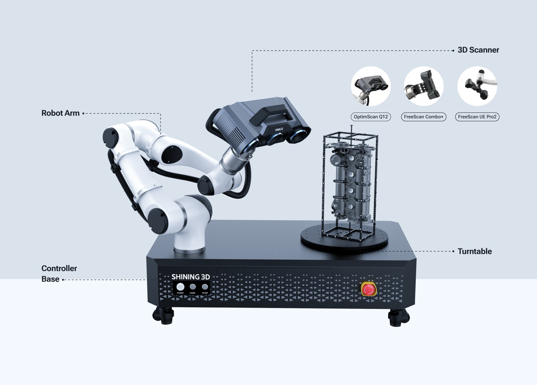
Inline 3D scanning for quality control is most relevant when a manufacturer wants optical measurement to take place as part of a repeatable production inspection process, rather than relying only on separate manual checks. SHINING 3D’s RobotScan Series is an automation solution combining a high-accuracy 3D scanner with an industrial robot or collaborative robot. Its stated role includes automated optical measurement for mass-production inspection; whether a particular configuration fits a production line depends on the component, inspection requirements and cell design.
Why put 3D scanning closer to the production process?
A 3D scanner for quality control captures surface geometry as digital data that can be assessed against an inspection reference. In manufacturing, the value of that data depends on more than capturing points: the measurement needs to address the part’s relevant geometry, produce interpretable results and fit the way inspection is performed. A production-line implementation therefore involves a measurement system and its operating sequence, not simply a scanner placed beside a machine.
Automated 3D measurement can be relevant where parts recur and the inspection task is sufficiently defined to be performed with a repeatable setup. RobotScan is described as an automated optical 3D measurement solution with high repeatability and high efficiency for mass-production inspection. That description positions the series for automation-oriented QC, but does not by itself establish a particular cycle time, detection rate, line-speed capability or connection to a given factory control system. Those are application-specific points to verify.
Inline inspection should also be distinguished from portable shopfloor inspection. A handheld or portable 3D scanner gives an operator flexibility to move around a component and capture data where the part is located. A robotic inspection arrangement instead coordinates the scanner and robot as an automated measurement setup. Both approaches can support manufacturing inspection, but they solve different workflow problems. A portable 3D scanner for shopfloor inspection may suit varied parts or onsite checks; an automated in-line inspection scanner is relevant when a defined measurement task is intended to run within a controlled cell or production sequence.
Where the RobotScan Series fits
The RobotScan Series includes RobotScan Q12, RobotScan UE Pro2 and RobotScan Combo+. The product information describes the series as configurable, with components such as the robotic arm, SHINING 3D scanner, turntable, fixtures, and control and inspection software tailored to application requirements. This modularity is a basis for discussing fit, not proof that every listed component is included in every system or that a particular line can be integrated without engineering work.
The Q12 configuration uses fringe projection and is described for small parts with complex surfaces, geometries or sharp edges. Listed examples include airfoils, brackets, connectors, gears, housings and electronic components. For a manufacturer considering a 3D scanner for electronic parts quality control, the relevant question is whether the target features and component size align with this small-part, detail-oriented use. The description does not provide a universal tolerance or guarantee that every electronic component is suitable.
RobotScan UE Pro2 uses handheld blue-laser scanning technology and is described as having strong material adaptability for black, shiny and reflective surfaces. Its stated application fit includes small and medium sheet-metal parts, casting housings, machined parts and mold components. It supports wireless and wired connectivity for on-site integration. For a 3D scanner for sheet metal inspection or mold inspection, the material and geometry may help guide model selection, while the specific inspection characteristics still need to be defined and validated for the part.
RobotScan Combo+ uses a hybrid light source and is described for batch inspection of small-to-medium castings and machined parts, as well as mixed-size components such as covers, trim pieces and assemblies. The product description positions it as an option for manufacturers with varied inspection needs. That makes it relevant to consider where a production mix includes different part types; it does not establish that one setup will inspect every part family without changes to fixtures, programs or configuration.
| Configuration | Described scanning approach | Stated fit to consider |
|---|---|---|
| RobotScan Q12 | Fringe projection | Small parts with complex surfaces, geometries or sharp edges, including listed fine-detail components |
| RobotScan UE Pro2 | Handheld blue laser scanning | Small and medium sheet-metal, casting-housing, machined and mold components; black, shiny and reflective surfaces are specifically noted |
| RobotScan Combo+ | Hybrid light source | Batch inspection of small-to-medium castings and machined parts, and mixed-size components |
The table summarizes the product descriptions; it is not a comparative performance test. The best-matched setup depends on the actual component, measurement features and required inspection process.
From optical capture to an inspection decision
A 3D inspection workflow generally has several linked stages. First, the system captures data from the physical part. The scan data then needs preparation and alignment for analysis. Where an approved CAD reference or other inspection reference is available, the data can be compared with it to examine dimensional differences, surface variation or specified characteristics. The resulting interpretation and report must then be usable by the people responsible for quality decisions.
This workflow helps explain why a 3D scanner for automated in-line inspection cannot be selected on scan speed or robot presence alone. The measurement plan must identify which surfaces and features matter, how the part is presented, how the scanner reaches the necessary areas, and how the resulting data will be assessed. For a 3D scanner for deviation inspection, the definition of the reference, alignment method and interpretation of deviations are part of the inspection method—not details that can be inferred from the scanner’s product name.
For first article inspection, the buyer should confirm that the planned measurement covers the characteristics required for the initial part evaluation and that the output supports the review process used by the quality team. RobotScan’s product information identifies automated measurement and mass-production inspection as relevant uses, but does not specify a universal first-article workflow, software functions or report format for every configuration. Those details should be confirmed in the proposed system scope.
Application fit: match the cell to the component
In automotive and general manufacturing, inspection needs may span small precision parts, sheet-metal components, castings and assemblies. The RobotScan descriptions provide examples across these categories, including electronic components, gears, housings, sheet metal, mold components and mixed-size covers or trim pieces. A 3D scanner for automotive parts inspection should therefore be evaluated against the actual component family and measurement objective, rather than treated as one universal application.
For a 3D scanner for mold inspection, the UE Pro2 description specifically includes mold components. The buyer still needs to identify the surfaces and features to be measured and decide whether the proposed scanning and robot arrangement can access them. Similarly, the Q12’s listed fine-detail use cases may be relevant when sharp edges or complex small-part geometry matter, but the product description alone does not establish a specific GD&T capability or tolerance result. If GD&T evaluation is required, confirm the software functions, measurement method and acceptance criteria for the intended configuration.
Other manufacturing keywords describe possible inspection needs, not universal claims about one RobotScan setup. A 3D scanner for MRO inspection, construction machinery manufacturing quality control or ship-hull inspection may involve different part sizes, access conditions and measurement objectives. The supplied RobotScan product information lists automotive, energy and heavy industry, engineering machinery and other transportation, marine, civil aviation, mold manufacturing and MRO among applicable industries. That industry coverage signals areas to assess; it does not prove that the same RobotScan configuration is appropriate for every component in each sector.
When the requirement is mobile onsite measurement rather than automated capture, a handheld scanner may be a more relevant workflow category. The RobotScan UE Pro2 itself is described as using handheld blue-laser scanning technology within an automation solution, with wired and wireless connectivity for flexible on-site integration. This does not make a robot-based cell equivalent to a standalone portable inspection workflow. The procurement question is whether the operation calls for an operator-led 3D scan at the point of need, a programmed automated sequence, or a combination of separate inspection methods.
System parameters and boundaries to check
The RobotScan Series product unit lists a measurable object size of up to 500 mm, turntable load capacity of up to 20 kg, robot working radius of 800 mm and system weight of 70 kg. These listed values should be read as the supplied series parameters, not as a guarantee that every part, robot path or station layout will fit. Before specifying an installation, confirm how the values apply to the proposed configuration and workpiece presentation.
Part size is only one fit question. The inspection plan also needs to account for the areas that must be visible to the scanner, surface characteristics, fixture arrangement and the robot’s reachable measurement positions. The listed 800 mm working radius is a robot parameter; it should not be mistaken for a scanner field of view or a guarantee of access to every feature. Likewise, the listed turntable capacity does not mean that a turntable is necessarily part of every system configuration.
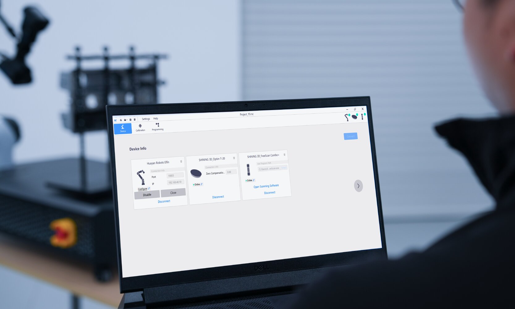
Manufacturers should also clarify how the proposed equipment will operate alongside existing production and quality processes. Confirm the needed control and inspection software, the scope of any fixtures or turntable, the configuration of the robotic arm, and the format and interpretation of inspection outputs. Where a line-side installation is intended, establish how operators load or present parts and how measurement results are handled. These are practical validation questions, not claims that the product unit specifies a particular interface, cycle time or factory-control integration.
A practical qualification path for inline 3D scanning
A useful evaluation starts with representative parts and a defined inspection question. Select the actual component families and identify the surfaces, dimensions or deviations that matter. This keeps the demonstration focused on the intended QC task instead of a general showcase of 3D scanning.
- Define the inspection objective: state whether the task concerns dimensional comparison, surface deviation, repeatable batch inspection or another specific quality check.
- Confirm part and setup boundaries: compare the workpiece size and weight with the supplied system parameters, and review fixture, turntable and robot-reach requirements for the proposed configuration.
- Match the scanner approach to the part: consider the Q12 for the described small, complex and fine-detail components; UE Pro2 where its listed material adaptability and sheet-metal, casting, machining or mold use cases are relevant; and Combo+ for the described mixed-size casting and machining inspection needs.
- Review the complete data path: confirm how capture, alignment, comparison, analysis and reporting will be carried out, including which software and inspection functions are in the proposed scope.
- Validate repeatability for the intended task: use the same parts, setup and inspection conditions that represent the intended production use, and agree in advance how results will be reviewed. The product description’s repeatability statement does not replace application-specific acceptance evidence.
- Assess the production fit: determine whether the proposed arrangement suits the actual operating sequence and whether inspection outputs can be acted on by the responsible quality team. Do not assume a target cycle time or control-system connection without documented confirmation.
This approach separates what is described about the equipment from what must be established for a specific factory. It also gives engineering and quality teams a common basis for discussing the scanner, robot, fixtures, software and inspection process as one system.
Conclusion: a role defined by the inspection task
RobotScan’s documented fit is automated optical 3D measurement for manufacturing inspection, with three configurations aimed at different part and surface requirements. Q12 is described for small, complex, fine-detail components; UE Pro2 for small and medium parts including sheet metal, castings, machined components and molds, with material adaptability noted for black, shiny and reflective surfaces; and Combo+ for batch inspection across stated casting, machining and mixed-size component examples. The series can be configured with robotic equipment, scanners, turntables, fixtures and software according to application requirements.
For manufacturers researching a 3D scanner for quality control, the practical decision is not simply whether a scanner can capture a 3D surface. It is whether the specific configuration can perform the required measurement on the target part, in a suitable repeatable setup, with results that fit the quality workflow. RobotScan is therefore best assessed through representative components, explicit inspection criteria and confirmation of the proposed system scope. Inline automation and portable onsite 3D scanning are related but distinct approaches; the right one depends on where and how the inspection must be performed.
Frequently asked questions
What is RobotScan’s role in inline 3D inspection?
RobotScan is an automation solution combining a high-accuracy 3D scanner with an industrial robot or collaborative robot. Its stated application includes automated optical measurement with high repeatability and high efficiency for mass-production inspection. Specific line integration, cycle time and inspection results depend on the proposed configuration and application.
How do RobotScan Q12, UE Pro2 and Combo+ differ in stated application fit?
RobotScan Q12 uses fringe projection and is described for small, complex parts and fine-detail components. RobotScan UE Pro2 uses handheld blue-laser scanning technology and is described for small and medium sheet-metal, casting-housing, machining and mold parts, including black, shiny and reflective surfaces. RobotScan Combo+ uses a hybrid light source and is described for batch inspection of small-to-medium castings and machined parts, as well as mixed-size components.
Can the RobotScan Series be used for first article inspection?
The RobotScan Series is described for automated optical measurement and mass-production inspection, and first article inspection is a relevant manufacturing QC task. The supplied product information does not define a universal first-article workflow for every configuration. Confirm the required characteristics, inspection method, software scope and report requirements for the specific application.
Which system limits should be checked before specifying a RobotScan setup?
The supplied RobotScan Series parameters list measurable object size up to 500 mm, turntable load capacity up to 20 kg, robot working radius of 800 mm and system weight of 70 kg. Confirm how these values apply to the proposed configuration, part presentation, fixtures and robot reach. They do not alone establish cycle time, access to every feature or compatibility with a particular production line.
Tem questões ou precisa de mais detalhes?
Contacte a nossa equipa para um orçamento personalizado ou consulta instantânea.
Solicitar orçamento
Preencha o formulário abaixo e a nossa equipa entrará em contacto com uma proposta personalizada.
Chat direto do WhatsApp
Prefere conversar em tempo real? Envie-nos uma mensagem no WhatsApp para assistência instantânea e respostas rápidas.
- Obter orçamento personalizado
- Partilhar fotos ou documentos
- Discuta as suas necessidades diretamente
Geralmente responde em 5–30 minutos durante o horário de expediente.