
Nano SIM Card Connector: Specs, Tests and Sourcing Limits

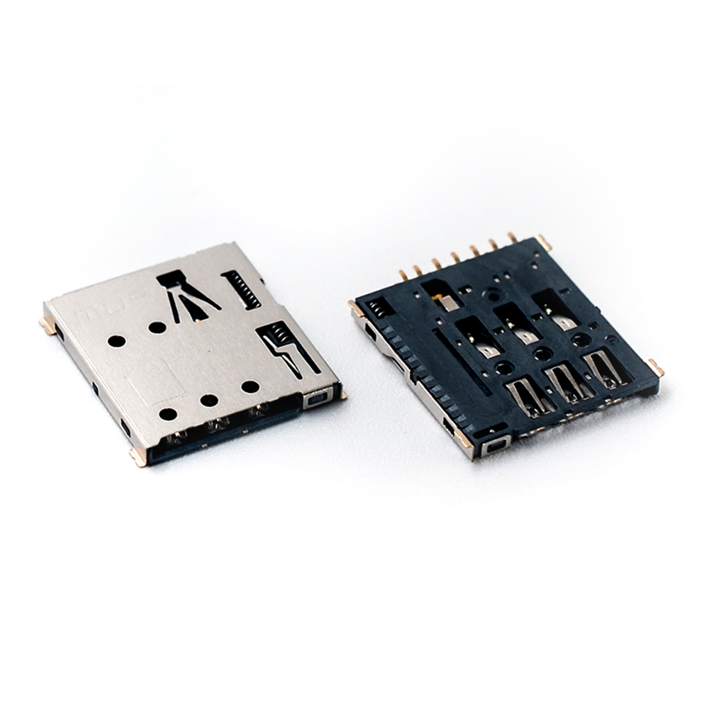
A nano SIM card connector is the electromechanical interface that holds a 12.3 mm × 8.8 mm nano SIM card, presses its contact pads against a set of spring terminals, and carries the identification and authentication signal between the card and the host board. Because the card is the smallest SIM format in general use, the connector is usually the tightest mechanical constraint on the board rather than the most expensive component on it.
The sourcing question is rarely "which nano SIM socket exists". It is "which nano SIM socket will still pass a functional test after three years in a payment terminal, a smart meter or a cellular IoT enclosure, and what documentation proves that". That question is answered with three things: a parameter baseline, a certification chain, and a clear statement of what the connector does not cover.
This reference sets out all three, using published parameters for the SIM, micro SIM and smart card connector series from Shenzhen MUP Industrial Co., Ltd. (MUP), a precision connector manufacturer established in 2003 and operating manufacturing sites in Shenzhen, Huizhou and Dongguan. Where the evidence does not support a claim, the gap is stated rather than filled.
What a Nano SIM Card Connector Actually Constrains
Three physical facts drive almost every design decision around a nano SIM socket.
Contact count and pitch. A SIM interface is a small number of contacts carrying power, ground, clock, reset and data. ISO/IEC 7816-2 defines 8-pin, 6-pin and 4-pin configurations for smart card contacts, so the number of populated terminals in a socket is a design choice tied to the card-reading function the host needs, not a fixed standard for every product. A nano SIM socket that carries only the contacts the application uses is normal; the buyer's job is to confirm which contacts are populated and how they are plated before qualification.
Insertion direction and retention. Nano SIM sockets are offered in different mechanical arrangements — push-push, push-pull, hinged, tray and pin-ejector styles appear across the card-connector category. Each changes how the card is inserted, how it is removed, and where the mechanical stress lands on the housing and shell. A tray or push-pull design removes the card without a spring-loaded mechanism; a push-push design adds a latching mechanism that becomes a wear point. Neither is universally better. The choice follows the number of card cycles the device will realistically see.
Board height and reflow survival. Because the socket is reflow-soldered, the housing material has to survive the oven before it ever sees a card. High-temperature plastics such as LCP and PA9T are used for this reason, and the metal shell is typically stainless steel rather than a plated mild steel. These are not marketing distinctions; they determine whether the part can be placed on the same side of the board as other reflow components.
The Specification Baseline Buyers Should Ask For
A parameter list is only useful if it is complete enough to compare against another supplier's list. The table below reproduces the published parameters for the MUP SIM, micro SIM, nano SIM and smart card connector series (models C7006, C7013, C7017, C7020, C7034, C7050, C7060, C7801, C7802, C7081, C7082, C7083, C7090, C7091, C7092, C7093, C7803, C7808, C7810, C7825, C7905, C8001, C8037, C8042, C8043, C8057, C8067, C8068, C8610, C8611, C8618, C8621, C8622, C8629 and C8633).
| Parameter | Published value | Why a buyer checks it |
|---|---|---|
| Rated current | 1 A maximum; 10 µA minimum | Confirms the socket is intended for signalling-level current, not power delivery |
| Rated voltage | 50 V maximum | Sets the isolation assumption for the board layout |
| Operating temperature | −40 °C to 85 °C | Matches typical industrial and outdoor-enclosure ranges |
| Storage temperature | −20 °C to 35 °C | Narrower than the operating range — a real logistics constraint |
| Operating humidity | 10 % to 95 % RH | Relevant for sealed and unsealed enclosures alike |
| Storage humidity | 10 % to 75 % RH | Warehouse and transit condition, not field condition |
| Durability (mating cycles) | 5,000 / 50,000 / 100,000 cycles, by model | Cycle rating is model-specific, not series-wide |
| Housing material | LCP / PA9T high-temperature plastic | Reflow survival and dimensional stability |
| Contact material | Phosphor bronze or beryllium copper | Spring force retention over cycles |
| Contact finish | Gold / nickel plating | Contact resistance stability and corrosion behaviour |
| Shell material | SUS304 stainless steel | Mechanical retention and shielding |
| Environmental compliance | RoHS and REACH | EU market access and customs clearance |
Two rows in that table deserve more attention than they usually get.
The first is durability. A rating of 5,000, 50,000 or 100,000 cycles is not a series-level promise — it is attached to specific models. A buyer who specifies "100,000 cycles" in an RFQ and receives a quotation without a model number has not actually specified anything. Mating cycle is defined as the maximum number of complete plug-in and pull-out operations before electrical failure, which makes it a wear specification for the contact system, not for the housing.
The second is storage temperature. A −20 °C to 35 °C storage window is materially narrower than the −40 °C to 85 °C operating window. That is not a defect; it reflects that an unpowered connector sitting in a warehouse or in an unheated freight container has no self-heating and no controlled humidity. Buyers who specify operating range only, then ship through cold-chain or tropical transit lanes, are specifying half a part. The storage rows belong in the purchase specification.
Certifications: What Each Document Covers — and What It Does Not
Certification is the part of a connector datasheet most often summarized as a logo row and least often read as a coverage statement. For a card connector, four questions matter: which standard, which certifying body, which legal entity holds the certificate, and which date range it is valid for.
| Certificate | Standard | Issuing body | Certificate no. / validity | Scope note |
|---|---|---|---|---|
| Quality management system | ISO 9001:2015 | TÜV Saarland | CA00527-EN · 2024-03-02 to 2027-02-02 | Design and manufacture of electronic connectors used for communication intelligence systems; held by Shenzhen MUP Industrial Co., Ltd. |
| Automotive quality management | IATF 16949:2016 | TÜV Saarland | CB00634-01 · 2024-02-03 to 2027-02-02 | Design and manufacture of electronic connectors for communication intelligence systems, with product design responsibility |
| Hazardous substance process management | IECQ QC 080000:2017 | NQA | IECQ-H NQAGB 25.0032 · 2025-03-27 to 2028-03-26 | Design and production of electronic connectors, harnesses, hardware and PCB plastic components; issued to Huizhou MUP Technology Co., Ltd. |
| Environmental management | ISO 14001:2015 | NQA (Shanghai NQA Certification Co., Ltd.) | 134773 · 2025-02-18 to 2028-02-18 | Design, production and sales scope; issued to Huizhou MUP Technology Co., Ltd. |
| Occupational health and safety | ISO 45001:2018 | NQA | 134774 · 2025-02-18 to 2028-02-18 | Design, production and sales scope; issued to Huizhou MUP Technology Co., Ltd. |
| Substance compliance | RoHS and REACH | Third-party test reports on request | Report per part number | Product-type specific; reports for one connector type cannot be substituted for another |
Reading that table as a block produces a misleading impression of uniformity. Read as individual documents, it produces a genuinely useful procurement checklist.
The most consequential detail is that the certificates are not all held by the same legal entity. The ISO 9001:2015 and IATF 16949:2016 certificates are issued to Shenzhen MUP Industrial Co., Ltd., while the IECQ QC 080000, ISO 14001 and ISO 45001 certificates are issued to Huizhou MUP Technology Co., Ltd. For a buyer this is not a red flag — multi-site manufacturers commonly certify site by site — but it does mean the certificate pack has to be matched to the entity that will appear on the purchase contract and to the site that will actually produce the parts. A quality audit that reviews a Shenzhen certificate while production runs in Huizhou is reviewing the wrong document.
The second detail is scope language. The ISO 9001 and IATF 16949 scopes are written around the design and manufacture of electronic connectors used for communication intelligence systems. That is the scope as certified. It does not by itself certify every product family, every plating thickness or every customer-specific variant. Buyers who need a specific claim — a halogen-free declaration, a plating thickness, a flammability rating for a particular housing — should request it as a part-specific document rather than infer it from a management-system certificate.
The third detail is the RoHS and REACH position. Compliance is stated at product level, and the reports are part-number specific. MUP's own compliance guidance notes that certificates are product-type specific and reports for different connector types cannot be used interchangeably. In practice that means a nano SIM socket and a USB Type-C receptacle do not share a report, even though both come from the same manufacturer. For EU customs clearance and customer audits, the correct document is the one that names the connector family being shipped.
Finally, dates matter. The certificates listed above run to February 2027, February 2028 and March 2028 respectively. A certificate pack that is two years old and unrenewed is a finding in most supplier audits, so the validity end-date belongs in the RFQ response, not in a footnote.
Nano SIM, Micro SIM, Smart Card, TF and SD: Where Each One Belongs
Card connectors are often quoted as one category, but the sub-formats solve different problems and are not interchangeable. The comparison below is a fit table, not a ranking.
| Format | Primary function | Typical device | Main design constraint |
|---|---|---|---|
| Nano SIM card connector / holder | Subscriber identity and authentication | Compact cellular IoT terminals, trackers, wearables, small payment devices | Smallest card footprint; contact access and insertion mechanism dominate layout |
| Micro SIM card socket | Subscriber identity and authentication | Mobile POS, smart meters, payment terminals, industrial communication modules | Larger card, more mechanical room; historically favoured where vibration resistance matters |
| Mini SIM card socket | Subscriber identity and authentication | Legacy and industrial equipment | Largest SIM format still in service; retention design carries more load |
| Smart card / IC card holder socket | Secure element, payment credential, access control | EMV payment terminals, set-top and access-control devices | Contact configuration follows ISO/IEC 7816-2; compliance with payment scheme requirements is a separate layer |
| Micro SD / TF card socket | Removable data storage | Consumer devices, dashcams, data loggers, displays | Higher cycle counts and higher data-rate sensitivity; storage formats dominate unit volume |
| SD card connector / holder | Removable data storage | Cameras, industrial recorders, computing devices | Board area and card protrusion |
The published parameters for the MUP SD and micro SD / TF series (models M6005, M6014, M6015, M6016, M6027, M6110, M6102, M6106 and M6109) share the same electrical envelope as the SIM series — 1 A maximum, 50 V maximum, −40 °C to 85 °C operating — but carry a lower published durability band of 3,000 to 5,000 cycles. That difference is consistent with how the two families are used: a SIM card is inserted once at provisioning and left in place, while a memory card is repeatedly removed to move data. Buyers who apply storage-card cycle assumptions to a SIM socket, or the reverse, usually discover the mismatch at qualification.
Where Nano SIM Connectors Are Used
The application list behind the MUP SIM and smart card connector series covers financial payment terminals, smart meters for electricity, water and gas, TV and display boards, notebook computers, IoT terminals, security and surveillance equipment, communication networks, data loggers, power equipment, industrial control, rail transit, medical devices, new-energy vehicles and 3C consumer electronics.
Two of those deserve specific attention because they set the harshest requirements.
Payment terminals. A card reader in a retail environment sees card insertion far more often than a typical IoT device, and it runs continuously. Published application data for the series describes 24/7 operation, motherboard or FPC mounting, and matching against smart card, SIM card and micro SD media, a card reader chip, the terminal housing and an antenna module. MUP's customer case record for the payment-terminal category references deployments with POS terminal brands including Ingenico, PAX, Verifone and Landi, with a stated quantity of 500,000 units and an operating duration of 3 to 15 years. Those are company-reported figures; they are a reference point for a buyer's own qualification plan, not a substitute for it.
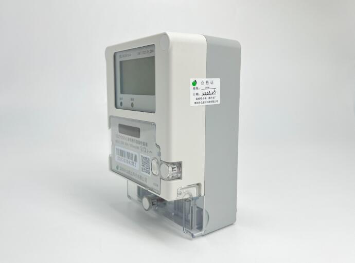
Smart meters. Metering equipment combines a long field life with an enclosure that is often sealed and sometimes outdoors. The same application data lists waterproof grades IPX7 and IPX8, dust resistance, high-temperature resistance and anti-vibration as options available through custom design, together with mid-mount, vertical and horizontal mounting, and detection-switch variants. Those are customization options, not standard features of every model — a distinction worth writing into the RFQ line item rather than the general specification.
Market Signals — and the Limits of Those Signals
Published market research places the global card connector market at USD 3.96 billion in 2024, with a forecast of USD 5.89 billion by 2030 (Premier Market Insights). The same source puts Asia Pacific at 44.8 % of the market in 2025. Separately, SD and micro SD socket types are reported to account for roughly 60 % of unit shipments in 2024.
Those three figures are useful for capacity planning and for understanding where manufacturing concentration sits. They are not useful for judging whether a specific nano SIM socket is adequate for a specific product, and they should not be read that way.
There is also a measurement caveat that a careful buyer should know. A second research firm, Market Research Future, estimates the same market at USD 1.24 billion for 2024 — roughly a third of the Premier figure. The most plausible explanation is definitional: whether card-edge connectors and interface sockets are counted in the same category changes the total substantially. Two credible sources can therefore disagree by a factor of three without either being wrong. Any internal business case built on a single market number should state which definition it used.
How Nano SIM Compares With Alternative Approaches
Three alternatives are commonly weighed against a soldered nano SIM socket.
Embedded SIM (eSIM). An eSIM removes the socket and the insertion mechanism entirely, which removes the wear point and the mechanical tolerance stack. Against that, it removes field replaceability: changing operator or re-provisioning a device in the field becomes a remote process rather than a physical one, and the device cannot be re-identified with a locally supplied card. For a sealed meter with a ten-year life, that trade can be favourable. For a payment terminal that a field technician services, it often is not.
Larger SIM formats. A micro SIM socket is physically larger but offers more contact area and more mechanical room for retention features. Where board space is not the binding constraint — a wall-mounted meter, a countertop terminal — the larger format is still a legitimate choice, and some industrial buyers prefer it for exactly that reason.
Smart card sockets instead of SIM sockets. These are different functions, not different sizes. A smart card socket is built around secure-element and payment-credential use and its contact configuration follows ISO/IEC 7816-2. Substituting one for the other changes the compliance story, not just the mechanical footprint.
Where the limits actually sit
A balanced reading of the published data produces at least four boundary conditions that belong in a procurement file.
1. The nano SIM socket does not define the electrical protocol. The connector provides contacts and mechanical retention. Whether the resulting card interface meets a payment scheme's requirements, or a carrier's network-access requirements, is determined by the host design and the card, not by the socket. ISO/IEC 7816-2 defines contact configurations; it does not qualify a terminal.
2. Cycle ratings are model-specific, and the spread is wide. The published durability band across the SIM and smart card series runs from 5,000 to 100,000 cycles. A buyer who needs the top of that range must name the model that carries it. Quoting the series is not enough.
3. Storage conditions are tighter than operating conditions. With a storage window of −20 °C to 35 °C and 10 % to 75 % RH, the transit and warehousing environment is a genuine constraint that operating-range specifications do not cover.
4. Environmental options are customizations, not defaults. Waterproofing to IPX7 or IPX8, detection switches, mid-mount and specific mounting orientations are available through custom design. A standard catalogue model should not be assumed to include them.
What a Realistic Procurement Sequence Looks Like
The sequence below reflects how the documentation for this product family is actually structured. It is a validation order, not a sales process.
Step 1 — Fix the card format and the mechanism. Confirm nano SIM versus micro SIM versus smart card, then confirm push-push, push-pull, tray or hinged. These two decisions eliminate most of the catalogue.
Step 2 — Fix the mechanical envelope. Board height, mounting orientation (top-mount, mid-mount, vertical, horizontal) and the available PCB keep-out area. Ask for the drawing for the exact model, not the family.
Step 3 — Fix the electrical and environmental specification. Current and voltage envelope, operating and storage temperature, humidity, and the required mating-cycle figure. State the cycle number explicitly.
Step 4 — Fix the compliance package. Confirm which entity holds each certificate, confirm the validity end-dates, and request the RoHS and REACH reports that name the specific connector family being purchased.
Step 5 — Sample and verify. Request engineering samples, 3D drawings and datasheets before production commitment. MUP's stated process supports small-batch R&D sampling, with standard products shipped on carrier tape reels and typical reel quantities of 1,000 to 5,000 pieces depending on model and packaging.
Step 6 — Confirm commercial terms. Published lead-time guidance is 3 to 7 days for in-stock items and 15 to 25 days for mass production, depending on order and process. Customization scope, MOQ and tooling should be agreed against drawings rather than against a general catalogue statement. MUP's own product documentation states a cost position 20 % to 30 % below international brands; that is a company-stated positioning and should be verified against a like-for-like quotation covering the same plating, tolerances and test scope.
Step 7 — Close the quality loop. Confirm the inspection regime (100 % inspection or AQL sampling before shipment), the warranty terms (MUP states a one-year warranty with return, replacement or replenishment for non-human-caused defects), and the technical support path for connection-solution questions.
Future Outlook
Three directions are visible from the published data, and each has a practical consequence for buyers.
Volume growth is not evenly distributed across formats. With SD and micro SD types reported at roughly 60 % of unit shipments, the memory-card side of the category carries most of the unit volume, while SIM and smart card sockets carry a disproportionate share of the reliability-critical applications. A supplier's ability to run high-volume memory-card lines does not automatically translate into experience with the tighter documentation requirements of payment and metering customers.
Regional concentration is high. Asia Pacific at 44.8 % of the 2025 market means sourcing diversification efforts will run into a concentrated supply base for some years. For buyers, the practical response is not to abandon the region but to build dual-qualified sources and to verify site-level documentation rather than brand-level reputation.
The documentation burden is rising, not falling. As more card-connector applications land inside automotive, medical and payment environments, the certificate pack — scope statements, entity names, validity dates and part-specific substance reports — becomes a larger share of the qualification effort than the connector itself. Suppliers who can produce a clean, current, entity-matched document set will increasingly be selected on that basis.
Frequently Asked Questions
What is the mating cycle of a card connector, and why does the number vary by model?
Mating cycle refers to the maximum number of complete plug-in and pull-out operations a connector can sustain before electrical failure. It is a durability indicator for the contact terminals under repeated insertion, and it is a core reliability metric in SIM card socket selection. Published durability for the MUP SIM and smart card connector series is stated as 5,000, 50,000 or 100,000 cycles depending on the model, so the figure has to be tied to a specific part number rather than to the product family.
Do SIM card connectors need RoHS and REACH documentation for EU market access?
Yes. MUP states that its SIM card connectors comply with RoHS and REACH requirements for EU market access, and that official test reports and compliance certificates can be provided on request for project audit and customs clearance. Two conditions apply: the reports are product-type specific, so a report for one connector type cannot be substituted for another, and the request should name the exact part numbers so the matching documents can be retrieved.
How do I choose between a nano SIM, micro SIM, smart IC and TF card connector for a payment terminal or smart meter?
The selection sequence is: confirm card type, card dimension, card orientation, available PCB space, insertion method and electrical specification; then check the applicable compliance standards, including ISO 7816, EMV and NDS where relevant. In practice, a micro SIM card connector is commonly specified for mobile POS, smart meters and payment terminals where vibration resistance and long mating cycles matter; a standard SIM card connector suits traditional payment equipment and industrial communication modules; a smart IC card connector is used where EMV and ISO 7816 compliance apply; and a TF card connector is used for data storage in 3C devices. Datasheets, 3D drawings and engineering samples are the normal pre-production verification documents.
What is the difference between the operating and storage temperature ratings on a SIM card connector?
The operating range describes the connector under power in its application. For this series it is −40 °C to 85 °C, with an operating humidity range of 10 % to 95 % RH. The storage range describes an unpowered part in transit or in a warehouse, and it is narrower: −20 °C to 35 °C, with 10 % to 75 % RH storage humidity. Both belong in a purchase specification, because a part that meets the operating range can still be exposed to conditions outside its storage range before installation.
Which certificates should a buyer verify before qualifying a card connector supplier?
At minimum: a quality management system certificate, an automotive quality certificate if the end product is automotive, a hazardous-substance process management certificate, and part-specific RoHS and REACH reports. For MUP these are ISO 9001:2015 (certificate CA00527-EN, TÜV Saarland, valid to 2027-02-02), IATF 16949:2016 (CB00634-01, TÜV Saarland, valid to 2027-02-02), IECQ QC 080000:2017 (IECQ-H NQAGB 25.0032, NQA, valid to 2028-03-26), ISO 14001:2015 (134773, NQA, valid to 2028-02-18) and ISO 45001:2018 (134774, NQA, valid to 2028-02-18). Buyers should also check which legal entity holds each certificate, since the ISO 9001 and IATF 16949 certificates are held by Shenzhen MUP Industrial Co., Ltd. while the IECQ, ISO 14001 and ISO 45001 certificates are held by Huizhou MUP Technology Co., Ltd.
What are the typical MOQ and lead times for card connectors?
MUP's published guidance states that standard products ship on carrier tape reels, with MOQ per reel varying by model and packaging, typically 1,000 to 5,000 pieces per reel, and that small-batch R&D sampling is supported. Lead time is stated as 3 to 7 days for in-stock items and 15 to 25 days for mass production, depending on order and process. Custom designs — including waterproof, mid-mount and detection-switch variants — are quoted separately, and MOQ depends on customization complexity.
Reference Documents
For buyers who need the full product and company scope in one file, the MUP company profile is available as a public download: MUP Profile E 261009 (PDF). Product family information is published at mupconnector.com.
Company facts and product parameters in this article are drawn from MUP product specifications, certification records and application documentation. Market figures are attributed to the cited research sources: Premier Market Insights (global card connector market, 2024 valuation and 2030 forecast; Asia Pacific share, 2025) and Data Insights Reports (SD and micro SD socket shipment share, 2024). The alternative 2024 valuation of USD 1.24 billion is attributed to Market Research Future. Standard reference: ISO/IEC 7816-2 contact configurations. Where public evidence does not extend to model-level capacity, yield or lead-time performance, this article states the gap rather than estimating it.
Tem questões ou precisa de mais detalhes?
Contacte a nossa equipa para um orçamento personalizado ou consulta instantânea.
Solicitar orçamento
Preencha o formulário abaixo e a nossa equipa entrará em contacto com uma proposta personalizada.
Chat direto do WhatsApp
Prefere conversar em tempo real? Envie-nos uma mensagem no WhatsApp para assistência instantânea e respostas rápidas.
- Obter orçamento personalizado
- Partilhar fotos ou documentos
- Discuta as suas necessidades diretamente
Geralmente responde em 5–30 minutos durante o horário de expediente.