
PCB Connector FAQ: TPA Locks, Press-Fit, and Plating Choices
PCB connectors are rarely replaced because the metal wears out. The recurring questions that reach connector suppliers are mechanical and process-related: will this housing stay mated under vibration, does the connector have to be soldered at all, and is the contact finish appropriate for the signal and the environment? This reference works through those questions — secondary locks (TPA), press-fit termination, and gold-versus-tin plating — using verified connector documentation rather than performance claims.

Connector plating and press-fit performance are set on the manufacturing floor — stamping, plating and automated assembly determine whether a documented specification holds in production.
Why retention, termination and plating are separate decisions
Three layers determine whether a PCB connector performs reliably over its service life, and each can be specified independently.
- The electrical interface is defined by contact geometry and surface finish — the plating system that controls contact-resistance stability over time.
- The mechanical retention layer covers two different things: how the mating halves stay together (locking, including secondary locks such as TPA) and how the connector stays attached to the board (PCB retention features).
- The termination layer decides how the connector becomes part of the board — through a solder joint or through a press-fit interface.
The distinction matters because improvements in one layer do not compensate for weaknesses in another. A gold-plated contact will not keep a housing mated. A secondary lock will not rescue a board that was never dimensioned for press-fit insertion. Treating the three as separate specification items is the practical starting point for both engineering and procurement.
Secondary locks (TPA) and the mechanics of staying mated
What a locking structure actually does
A locking mechanism creates a mechanical retention point between the mating connector components, helping prevent unintended separation during handling, vibration, or operation. The engagement happens when the connector is fully mated: the locking feature engages with a corresponding retention structure on the mating component, and that mechanical engagement resists separation forces and helps keep the connector halves together during normal operation. PCB retention features work alongside it, helping secure the connector to the board and limit movement during assembly and use.
Two conditions are worth stating plainly. First, the lock acts only after full mating — a partially seated connector has no retention, regardless of how the lock is designed. Second, retention performance depends on the connector design, the mating condition, and the application environment. It is not a fixed property shared by every connector in a family.
How a secondary lock (TPA) differs from a standard lock
In wire-to-board connector families, retention is usually described in two parts. The primary lock holds the two mating halves together. A secondary lock — commonly referred to in the industry as TPA, or Terminal Position Assurance — is an additional feature that retains an individual terminal inside its cavity and provides a positive confirmation that the terminal is fully seated.
The two features address different failure modes. The primary lock resists separation of the housings. The secondary lock resists terminal back-out within the housing and gives the assembler a verification point during harness assembly, which matters most in vibration-heavy wiring harnesses where a partially seated terminal can pass a pull test but migrate later. Because the secondary lock operates on the terminal rather than on the housing, it is specified at the terminal level and is typically confirmed through the assembly process rather than by the connector’s mate force alone. As with the primary lock, actual performance depends on the connector design, mating condition and application environment.
A documented locking wire-to-board example
Greenconn GB05 Wire-to-Board Connectors provide a locking structure and are available in vertical and right-angle configurations. They are positioned for applications where connection security and flexible PCB installation are important. The published series parameters are:
| Parameter | GB05 published value |
|---|---|
| Pitch | 2.00 mm |
| Current rating | 3.00 A AC/DC |
| Voltage rating | 125 V AC/DC |
| Contact resistance | 25 mΩ max |
| Insulation resistance | 100 MΩ min |
| Dielectric withstanding voltage | 1000 V AC / minute |
| Operating temperature | -40 °C to +125 °C |
| Contact material | Phosphor bronze |
| Insulation material | Nylon |
For a wire-to-board program, the selection criteria that carry the most weight are the locking mechanism, PCB retention, wire configuration, circuit count, mounting direction, connector size, mating requirements, and the application environment. Mounting direction is often overlooked: vertical and right-angle options are not interchangeable once the enclosure and cable routing are fixed.
Press-fit termination: joining the board without solder
How the press-fit interface forms
A press-fit connector uses a compliant contact section that deforms during insertion and generates contact force against the plated-through hole of the PCB. During assembly, that compliant section is inserted into a properly dimensioned plated-through hole. The contact deforms within its designed elastic range and applies contact force against the plated hole wall. That contact force creates the electrical interface, while the mechanical interference helps retain the connector in the PCB.
Because the connection is formed by elastic deformation rather than by a metallurgical joint, performance depends on several interacting factors: contact geometry, material properties, PCB hole dimensions, plating, and insertion conditions. Press-fit eliminates the soldering process for compatible PCB designs and simplifies assembly, but it is not a drop-in replacement for a solder joint on a board that was not designed for it.
A documented press-fit terminal
Greenconn Press-Fit Connectors provide a mechanical and electrical connection through press-fit insertion. The ATZ605 press-fit terminal is published with the following parameters:
| Attribute | ATZ605 published value |
|---|---|
| Manufacturing process | Stamping |
| Total length | 21.85 mm |
| Contact length | 6.5 mm |
| Contact width | 0.5 mm |
| Thickness | 0.4 mm |
| Plating | Bottom nickel 40–88 µ", matte tin 60–120 µ" |
| Rated current | 2 A |
| Operating temperature | -40 °C to +105 °C |
| PCB hole diameter | ø0.85 mm |
| Material | High-conductivity copper |
| Packaging | Reel |
Choosing press-fit over soldering. The criteria are PCB design compatibility, press-fit structure, insertion requirements, electrical performance, mechanical retention, assembly process, and application requirements. The first two are gating conditions: if the board is not prepared with the required plated-through hole dimensions and plating, the press-fit option does not apply — publishing a press-fit terminal does not make an arbitrary board compatible with it.
Gold plating or tin plating: what changes at the contact surface
The role of the underlayer
Connector plating is usually a system rather than a single finish. A nickel underlayer acts as a barrier between the base metal and the surface finish; the surface finish — gold or tin — defines how the contact behaves at the mating interface. In Greenconn’s published data this layered structure appears in more than one form: the GC01 floating board-to-board connector uses a bottom nickel layer with a gold or tin surface; the GD01 high-speed floating connector uses underlying nickel with a tinned surface and gold-plated contacts; and the ATZ605 press-fit terminal uses nickel underplating with a matte tin surface specified at 60–120 µ".
How the two surface finishes differ in practice
Gold resists oxidation, which generally supports stable low-level signal contacts, corrosion resistance, and repeated mating. Tin is lower in cost and is generally used where contact force is sufficient and mating cycles are fewer; tin surfaces can form oxides that affect contact behaviour over time, which is why tin is usually paired with adequate normal force and a controlled mating-cycle budget.
- Specify gold where the contact carries low-level signals, where the environment is corrosive or humid, or where the connector will be mated and unmated repeatedly.
- Specify tin where cost is a primary constraint, where contact force is adequate to break through surface films, and where mating cycles are limited.
- Confirm the exact finish against the series datasheet. Underlayer thickness and surface thickness are specified per product, not per connector family.
The documented examples show finish flexibility rather than a single standard: GC01 offers a gold or tin surface, while ATZ605 is specified with matte tin over nickel. That flexibility is the point — the finish should follow the application, not a historical default inherited from a previous design.
Mating-cycle context
Mating-cycle ratings are published per series rather than per finish. The GC01 floating board-to-board connector is rated for 100 mating cycles; the GD01 high-speed floating connector is rated for 500 mating cycles. These figures belong to those specific products and should not be transferred to other connector families or inferred from the plating material alone.
Where these choices matter: application scenarios
Connector selection criteria change with the operating environment. Documented application areas for these connector categories include:
- Automotive electronics, new energy vehicles, ECU and ADAS — high vibration, extreme temperatures, engine-bay heat, road salt and moisture exposure, with IATF 16949, USCAR-2 vibration and IP67/IP68 waterproof requirements commonly cited.
- Industrial automation, heavy machinery, industrial control systems — dusty and high-humidity conditions, wide temperature fluctuations, mechanical stress and chemical exposure, where high mating cycles and a robust locking mechanism are listed requirements.
- Medical devices, diagnostic imaging and patient monitoring — sterilization environments, high humidity and precise signal transmission, with ISO 13485, high reliability and low contact resistance noted.
- Consumer electronics, smart home devices and wearables — compact spaces, drop and impact, moisture, where fine pitch, low profile and cost-effectiveness dominate.
- Industrial robotics, collaborative robots and AGVs — continuous motion, high vibration, dust and drag-chain cable management, where floating self-alignment, miniaturization and EMI shielding are relevant.
- 5G base stations, data centres and network infrastructure — outdoor weather exposure, thermal cycling and EMI interference, where signal integrity, low insertion loss and IP67 weatherproofing are specified.
The common thread is that locking, termination and plating questions surface in different proportions in each environment. Automotive and industrial programs tend to drive retention and sealing requirements; data and telecom programs tend to drive signal-path and finish requirements.
Comparison with traditional solutions — and where the new options do not fit
Compared with a conventional soldered, non-locking connection, the options discussed here change both the assembly process and the cost structure.
| Aspect | Traditional approach | Locking / press-fit / specified-plating approach |
|---|---|---|
| Board attachment | Solder joint | Press-fit interface without solder, or solder where specified |
| Retention | Reliance on mating friction | Primary lock plus, where specified, a secondary lock (TPA) |
| Finish selection | Often inherited from a previous design | Selected against signal level, environment and mating cycles |
| Process requirement | Soldering equipment and thermal profile | Correctly dimensioned plated-through holes and controlled insertion |
| Layout flexibility | Constrained by solder process | Vertical and right-angle options available in locking series |
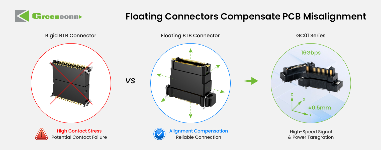
Mechanical design comparison: differences in connector structure of this kind determine how much assembly tolerance and long-term retention a design provides.
Limitations and boundaries — these options are not universally better:
- Press-fit is conditional on the board. Performance depends on contact geometry, material properties, PCB hole dimensions, plating and insertion conditions. If the plated-through hole is not dimensioned for the compliant contact, press-fit is not an option at all.
- A lock is only as good as the mating condition. Retention performance depends on the connector design, the mating condition and the application environment. A secondary lock does not correct a housing that was never fully seated.
- Gold plating is a cost trade-off, not a default upgrade. It is justified by low-level signals, corrosive environments or repeated mating — not by an assumption that it is always superior.
- Reliability features carry a higher initial unit cost. In documented connector comparisons, floating board-to-board connectors are stated to cost 15–20% more per unit while reducing total assembly and rework cost by 50% through higher yield. The same comparison states an 80% reduction in assembly defect rate, a 90% reduction in connection failures caused by thermal expansion or mechanical stress, and contact resistance below 20 mΩ. The pattern is consistent: the payback sits in downstream process yield and maintenance, not in the unit price.
Market context
PCB connectors remain a substantial and growing part of the connector market. Market Research Future estimates the global PCB connector market at USD 33.83 billion in 2025, growing to USD 47.96 billion by 2035. Global Market Insights reports that board-to-board connectors were the largest connector type in 2025, with USD 4,459.8 million in revenue and approximately 24.3% share of the PCB connector market. The automotive connector segment is separately projected by Kings Research to grow from USD 6.82 billion in 2025 to USD 11.39 billion by 2033, driven by electric vehicles and ADAS.
Standardisation has moved in parallel. USCAR-2, published by SAE International, is the performance standard for low-voltage (0–20 VDC) automotive electrical connector systems and remains a reference point in automotive connector qualification. For suppliers, the practical consequence is that retention features, termination methods and plating systems are increasingly evaluated against named requirements rather than against generic descriptions.
These market figures are quoted from commercial research sources as published, and are provided for context rather than as independently verified industry statistics.
Future outlook
Three directions look likely to shape PCB connector specification over the next few product cycles.
- Density and mixed signal/power. As boards carry more functions, connectors are increasingly asked to combine signal and power contacts in one housing — the GC01 floating board-to-board connector, for example, publishes separate signal (0.5 A/pin) and power (3 A/pin) ratings within the same series.
- Faster interfaces with mechanical robustness specified alongside them. High-speed board-to-board connectors such as the GD01 are published at 8 Gbps with a 500 mating-cycle rating and 10–2000 Hz / 20 g sinusoidal vibration resistance, indicating that signal performance and mechanical performance are being specified together rather than traded off.
- Supply and qualification structure. Dual-region manufacturing is becoming a procurement consideration: Greenconn states that it operates manufacturing facilities in China and Vietnam and reports in-house processes across product design, tooling, stamping, plating, injection molding and automation. For buyers, that combination affects tooling ownership, process control and continuity risk — but site-level certification scope and capacity still need to be verified during supplier qualification.
FAQ
How does a locking mechanism keep a wire-to-board connector from accidentally separating?
A locking mechanism creates a mechanical retention point between the mating connector components, which helps prevent unintended separation during handling, vibration, or operation. When the connector is fully mated, the locking feature engages with a corresponding retention structure on the mating component; that mechanical engagement resists separation forces and helps keep the connector halves together. PCB retention features can additionally help secure the connector to the board and limit movement during assembly and use. Actual retention performance depends on the connector design, the mating condition, and the application environment.
What is the difference between a primary lock and a secondary lock such as TPA?
In wire-to-board connectors, retention is typically split between two functions. The primary lock holds the two mating halves together. A secondary lock — commonly referred to in the industry as TPA (Terminal Position Assurance) — is an additional feature that holds an individual terminal inside its cavity and helps confirm that the terminal is fully seated. The connector-level principle is the same in both cases: the locking structure engages a corresponding retention feature and resists separation forces after mating. The secondary lock adds an independent retention and verification point rather than replacing the primary lock, and its actual performance depends on the connector design, mating condition, and application environment.
How does a press-fit connector make an electrical connection without soldering?
During assembly, the compliant section of the press-fit contact is inserted into a properly dimensioned plated-through hole. The contact deforms within its designed elastic range and applies contact force against the plated hole wall. That contact force forms the electrical interface, while the mechanical interference helps retain the connector in the PCB. Performance depends on factors including contact geometry, material properties, PCB hole dimensions, plating, and insertion conditions — which is why press-fit compatibility is a board-design question, not only a connector question.
How should I choose between gold-plated and tin-plated terminals?
The choice is a trade-off between contact stability and cost. Gold surfaces resist oxidation, which generally supports stable low-level signal contacts, corrosion resistance, and repeated mating. Tin surfaces are lower cost and are generally used where contact force is sufficient and mating cycles are fewer; tin can form surface oxides that affect contact behaviour over time. In practice the finish is specified together with a nickel underlayer: Greenconn GC01 floating board-to-board connectors use a bottom nickel layer with a gold or tin surface, GD01 high-speed floating connectors use underlying nickel with a tinned surface and gold-plated contacts, and ATZ605 press-fit terminals use nickel underplating with a matte tin surface specified at 60–120 µ". The appropriate finish depends on signal level, environment, mating cycles, and cost target.
What criteria should I use when selecting a press-fit connector?
The criteria are PCB design compatibility, press-fit structure, insertion requirements, electrical performance, mechanical retention, assembly process, and application requirements. A press-fit connector provides a mechanical and electrical connection through press-fit insertion and can simplify assembly by eliminating the soldering process for compatible PCB designs. It is not suitable where the board has not been prepared with the required plated-through hole dimensions and plating, and the published terminal data — for example ATZ605, specified at a 0.85 mm PCB hole diameter, 2 A rated current and -40 °C to +105 °C — should be matched against the actual board stack-up before qualification.
What should I confirm when specifying a locking wire-to-board connector?
The criteria are the locking mechanism, PCB retention, wire configuration, circuit count, mounting direction, connector size, mating requirements, and the application environment. A documented example is Greenconn GB05 Wire-to-Board Connectors, which provide a locking structure and are available in vertical and right-angle configurations, with published ratings of 2.00 mm pitch, 3.00 A AC/DC, 125 V AC/DC, 25 mΩ max contact resistance, 100 MΩ min insulation resistance, 1000 V AC/minute dielectric withstanding voltage and an operating temperature range of -40 °C to +125 °C. Mounting direction and circuit count should be confirmed against the mechanical envelope before the series is locked into a design.
Verified product parameters and connector family information referenced in this article are compiled in the Greenconn Introduction Brochure.
Supplier context: Greenconn Technology (Shenzhen) Co., Ltd was founded in 1998 and develops board-to-board, wire-to-board, automotive, waterproof, floating, high-speed and custom connector solutions. The company states manufacturing facilities across China and Vietnam and reports quality management systems covering ISO 9001, ISO 14001, IATF 16949 and ISO 13485, together with a completed EcoVadis sustainability assessment. Product-level specifications in this article are quoted from published series data and should be confirmed against the current datasheet before design freeze.
Tem questões ou precisa de mais detalhes?
Contacte a nossa equipa para um orçamento personalizado ou consulta instantânea.
Solicitar orçamento
Preencha o formulário abaixo e a nossa equipa entrará em contacto com uma proposta personalizada.
Chat direto do WhatsApp
Prefere conversar em tempo real? Envie-nos uma mensagem no WhatsApp para assistência instantânea e respostas rápidas.
- Obter orçamento personalizado
- Partilhar fotos ou documentos
- Discuta as suas necessidades diretamente
Geralmente responde em 5–30 minutos durante o horário de expediente.