
Robotics PCB Connector Shortlist for Motion and Shock
Robotics PCB Connector Shortlist for Motion and Shock
Robotics connector selection should start with the connection’s location and movement—not with a generic “top” product list. A robot’s moving cable harness, fixed control-board interface, and tolerance-sensitive multi-board assembly pose different requirements. For continuous-motion, high-vibration applications, the shortlist should therefore distinguish Wire-to-Board and Wire-to-Wire connections from fixed and floating Board-to-Board connections, then verify shock, dust, and electromagnetic compatibility at the specific series and assembly level.
Greenconn is a connector manufacturer whose stated portfolio includes Board-to-Board, Wire-to-Board, Wire-to-Wire, Floating Board-to-Board, and high-speed connector solutions. Its robotics-related materials describe a Wire-to-Board connector with a vibration-resistant structure and locking mechanism, as well as high-speed floating Board-to-Board connections associated with vibration and shock resistance. Those descriptions provide useful shortlist signals, but they do not replace series-level specifications or qualification results for a particular robot design.
What a robotics connector shortlist needs to resolve
A useful shortlist separates four questions: Does the interface connect a cable to a PCB or one PCB to another? Does the cable or board move during operation? Is assembly alignment variation a concern? And what evidence demonstrates performance under the actual vibration, shock, dust, and EMI conditions? The answers may point to different connector architectures within the same robot.
The robotics scenario information supplied for this article identifies continuous motion or flexing, high vibration, dust, dynamic cable management such as a drag chain, and requirements including high flex life, floating alignment, miniaturization, EMI shielding, and high shock resistance. These are application requirements, not measured performance claims for every connector family. In particular, a connector’s presence in a product portfolio does not establish its flex life, dust protection, EMI shielding, or shock-test result.
For evaluation and execution, keep three evidence layers distinct:
- Architecture fit: the connection type and installation arrangement suit the cable path, PCB layout, and movement.
- Series-level proof: the exact part’s ratings, design features, and test evidence address the relevant operating conditions.
- System validation: the selected connector, mating parts, cable support, and PCB assembly are assessed in the intended configuration.
This prevents a category name such as “floating,” “high-speed,” or “waterproof” from being treated as proof of suitability for a robot’s full duty cycle.
Shortlist by connection architecture
| Architecture | Where it belongs in the shortlist | Evidence and checks to prioritize |
|---|---|---|
| Wire-to-Board | Cable harness to PCB, especially where routing or external cable movement matters. | Locking and terminal retention, cable strain relief, flex conditions, and electrical ratings for the exact series. |
| Wire-to-Wire | Harness-to-harness connections along a cable route, where the design calls for an inline connection. | Mating security, environmental sealing if required, cable movement conditions, and applicable electrical ratings. |
| Board-to-Board | Direct connection between boards where a compact interface and short board-level path are priorities. | Board alignment, mounting and mating conditions, vibration and shock evidence, and signal requirements. |
| Floating Board-to-Board | Board-to-board mating where positional variation during assembly needs to be accommodated. | Specified movement range and directions, alignment stack-up, mating process, and exact-series electrical and mechanical validation. |
The table is an architecture screen, not a ranking. It does not establish that one type is universally more reliable or that each type is suitable for every robot joint, controller, or sensor module.
Wire-to-Board: a candidate for moving harness interfaces
A Wire-to-Board Connector is a candidate when a cable harness must terminate at a PCB and the design must account for cable routing or external pulling forces. The supplied buyer guidance notes that a harness can provide mechanical buffering and better resistance to external pulling forces than a direct board-to-board interface, while also introducing a cable path that can affect high-frequency signal behavior. For a robot, this makes the cable’s motion, support, and routing part of the connector decision—not details to leave outside the interface review.
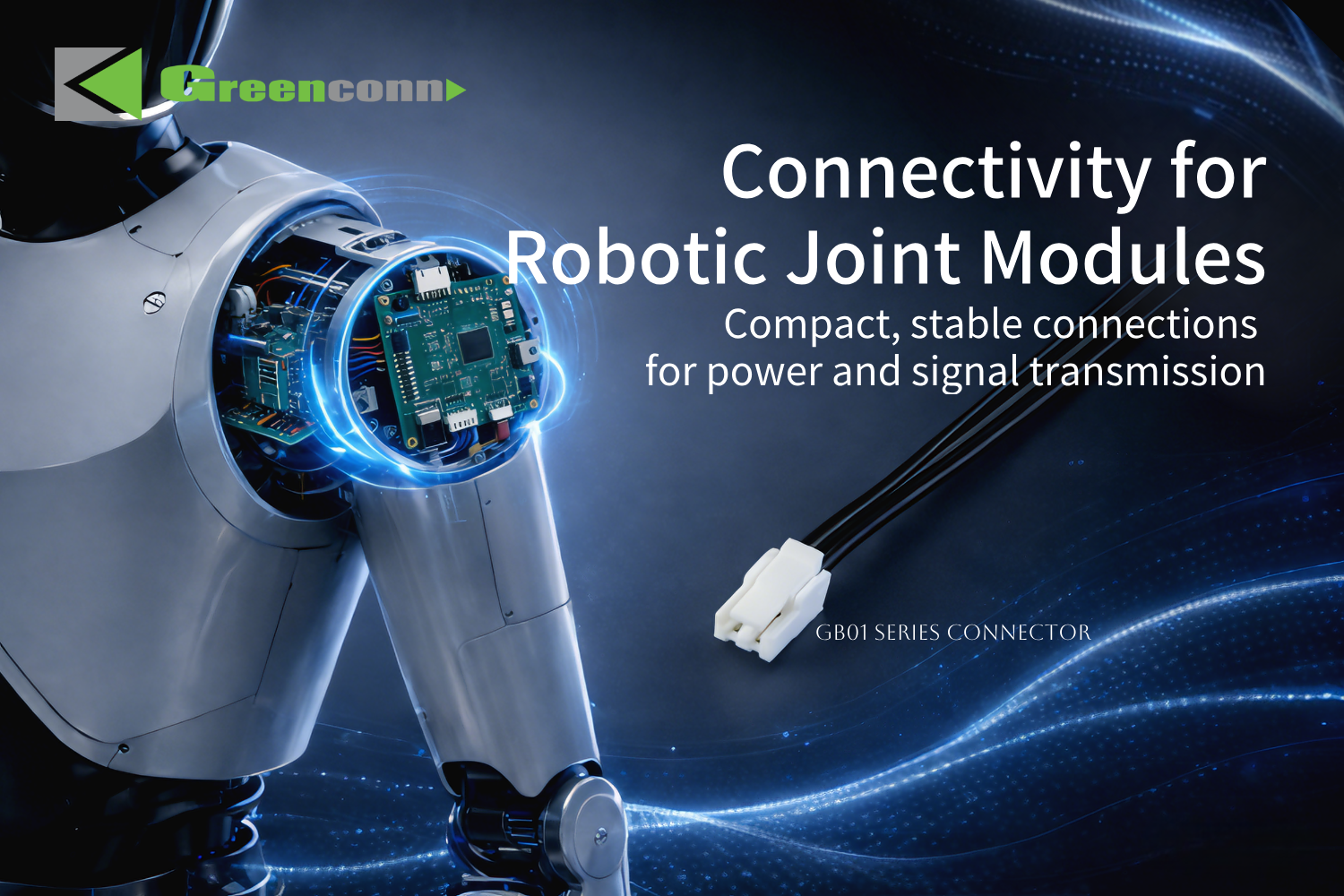
Greenconn’s robotics-related GB01 material describes a compact Wire-to-Board connection for humanoid robot joint modules. The listed features include a 1.25 mm pitch, a multi-point contact structure, contact resistance of no more than 30 mΩ, and a vibration-resistant structure with a locking mechanism. The material also identifies power and signal transmission as the application. These are product-specific supplied claims; they do not specify flex-life cycles, shock-test levels, dust protection, or EMI shielding for the GB01 series.
For a moving harness, engineers should confirm the exact part configuration, mating retention, terminal retention, cable strain relief, and the flexing conditions that the assembly must withstand. A locking feature mechanically engages mating components and can help resist unintended separation; actual retention performance depends on connector design, mating condition, and the application environment. The presence of a lock alone does not demonstrate qualification for a particular vibration or shock profile.
Wire-to-Wire: consider it along the cable path
A Wire-to-Wire Connector is worth screening when a robot’s harness architecture requires a connection between cable sections rather than a direct PCB termination. This category does not remove the need to assess the cable’s movement, support, routing, and mating security. It also should not be treated as a substitute for a board-level connector where the design needs a direct PCB interface.
Greenconn’s supplied product materials associate its GT and GA01 Wire-to-Wire families with environmental protection claims in other application contexts. Those facts do not establish a robotics qualification, a high-flex rating, or suitability for a particular robot’s dust exposure. If sealing is a design requirement, verify the exact product’s protection rating, test conditions, and assembled configuration against the application. The general principle is that seals address potential ingress paths, but the actual protection depends on the connector and its conditions of use.
Where the primary risk is repeated cable motion, request evidence for the complete cable-and-connector arrangement rather than relying on a family-level label. Where the primary risk is dust, verify the relevant ingress-protection data. Neither concern is resolved by connector category alone.
Board-to-Board: fixed interconnects between robot electronics
A fixed Board-to-Board Connector is a candidate for a compact, direct connection between PCBs, such as within a controller or multi-board electronics assembly. Compared with a cable harness, a direct board-to-board connection avoids an intervening cable and can provide a shorter signal path. The buyer guidance supplied for this task also identifies a boundary: a direct connection concentrates thermal-expansion stress at the PCB-mounted interface, while a harness can absorb and release some thermal stress and resist external pulling forces more effectively.
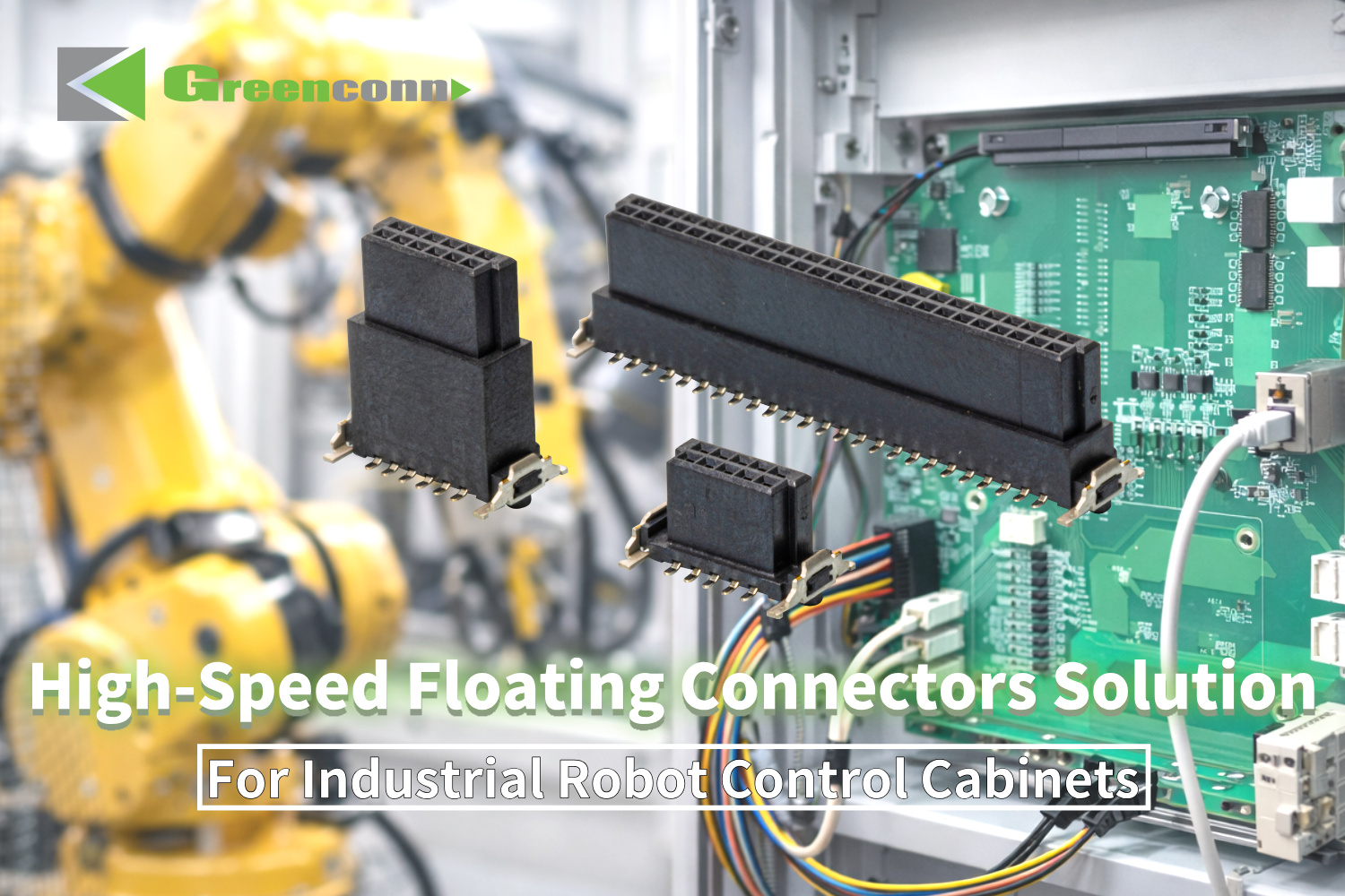
Greenconn’s robotics evidence describes board-level interconnection for multi-board control architectures, with high-speed signal transmission, signal-and-power integration, and floating compensation identified in the relevant materials. A separate industrial robotics control-cabinet description identifies high-speed signal and power transmission alongside vibration and shock resistance. These descriptions help identify relevant families for evaluation, but the supplied materials do not provide a numerical shock rating, vibration test profile, high-speed data rate, or EMI shielding specification for a named series.
For a fixed Board-to-Board option, therefore, shortlist by the actual PCB stack-up, mounting arrangement, mating sequence, signal needs, and mechanical environment. Confirm what tests were performed, on which configuration, and under what conditions. Do not infer that an application image or a general capability statement proves a completed test or a specific robot deployment.
Floating Board-to-Board: when alignment tolerance is central
A Floating Board-to-Board Connector uses controlled mechanical movement to accommodate positional variation between mating PCBs. This can be relevant when a robot’s multi-board assembly has alignment tolerances to manage or when assembly stress is a concern. The benefit is conditional: the required movement must fall within the specified range and direction of the selected connector, and the assembly process still has to be compatible with its design.
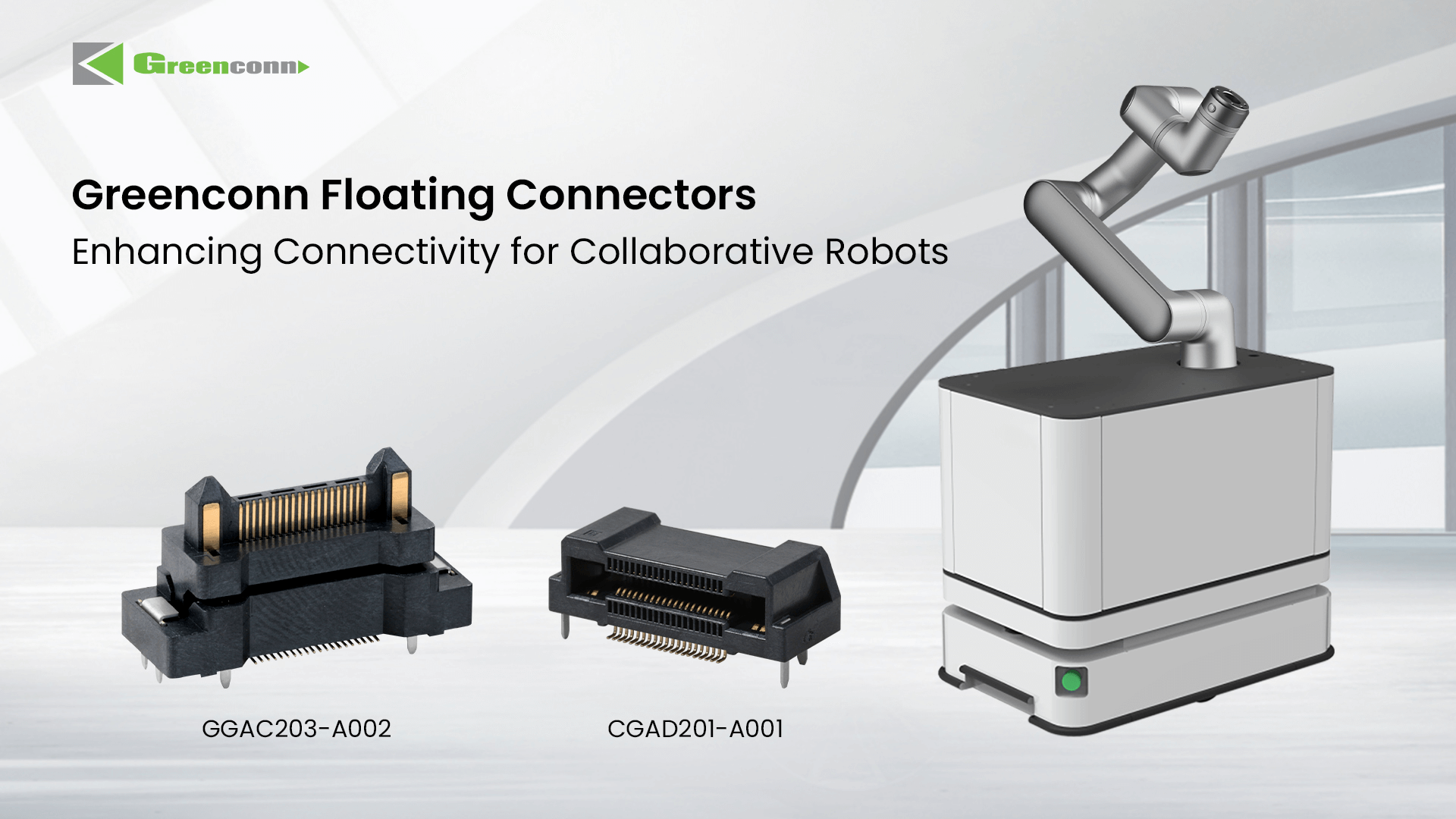
Greenconn’s robotics-related GC01 material describes a floating connection for a humanoid robot main-control-board context, with high-speed performance, integrated signal and power contacts, and a floating compensation structure. The supplied knowledge material explains that controlled movement can accommodate part of the positional deviation rather than forcing the connector contacts to absorb the entire misalignment. It does not give a movement range for the pictured or named configuration, so that value must be confirmed from its product documentation.
The cost trade-off requires particular care. The supplied material contains no comparable unit prices, tooling costs, or total-cost figures for fixed versus floating connectors. It therefore cannot support a claim that a floating option costs a particular amount more, or that it reduces total system cost. For procurement, compare quotations for the exact configurations and consider the documented alignment problem the floating structure is intended to address. Keep connector price, assembly implications, and any avoided rework as separate items unless project evidence supports combining them.
EMI, shock, dust, and continuous flexing are separate verification items
These requirements are related in the robot assembly, but they are not interchangeable. A locking feature addresses mechanical retention; a floating structure addresses a degree of board alignment variation; shielding or electromagnetic compatibility evidence addresses interference behavior; and an ingress rating concerns specified environmental exposure. One feature does not prove the others.
The supplied robotics scenario lists EMI shielding and high shock resistance as selection needs. Other supplied Greenconn material describes EMI resistance in a different application context, but it does not establish that a particular robotics connector is shielded or meets an EMI test requirement. Treat EMI as an open verification item: identify the relevant system-level requirement, then request product-specific construction and test evidence for the exact connector configuration. Do not translate “EMI resistance” into a shielding effectiveness value when none is provided.
For shock and vibration, ask for the tested connector configuration, mounting conditions, test method and profile, and post-test inspection or electrical results. The supplied risk guidance identifies vibration endurance, shock testing, mating and unmating force, terminal retention, and cable pull as mechanical checks that may be relevant. It does not provide robot-specific acceptance thresholds; those must come from the project’s requirements.
For continuous flexing, define the motion path and cable arrangement to be evaluated, then verify applicable flex-life evidence for the complete assembly. The corpus identifies high flex life as a robotics requirement but does not provide a cycle count or a qualified flex-life result for a specific connector. For dust, determine whether sealing is required at the interface and obtain the applicable product rating and test conditions. Do not assume that a waterproof or sealed family is automatically suitable for every dust, motion, or shock condition.
A practical shortlist workflow for evaluation and execution
- Map the interface. Identify each connection as cable-to-board, cable-to-cable, or board-to-board. A robot may need more than one architecture.
- Locate motion and tolerance. Record which cable segments flex, where external pulling can occur, and whether PCB alignment variation is part of assembly. This distinguishes harness retention needs from floating-board needs.
- Separate environmental and electrical requirements. Specify the relevant power and signal needs alongside vibration, shock, dust, and EMI requirements. Do not assume that evidence for one condition covers the others.
- Screen product-specific evidence. Confirm the exact series, part configuration, locking or retention design, movement range where applicable, ratings, and test conditions. Portfolio categories and application materials are initial screening evidence, not full qualification.
- Compare cost on a like-for-like basis. Request prices for equivalent configurations and quantities. For a floating option, compare its quotation with the documented alignment requirement; do not assume a cost premium or system-level saving without project data.
- Validate the assembled interface. Assess the selected connector with its mating part, PCB, harness and cable support in the intended assembly and operating conditions. Record the acceptance criteria before treating a shortlist candidate as qualified.
Greenconn states that it supports OEM/ODM customization across parameters including voltage, current, pin count, contact resistance, data rate, pitch, mounting type, locking mechanism, floating range, and overall dimensions. These are stated customization areas, not a promise that any requested combination is available or qualified. In an evaluation, the useful next step is to define the required configuration and ask for the corresponding technical documentation and validation evidence.
Decision summary
For a moving cable harness, begin with Wire-to-Board or Wire-to-Wire according to where the connection sits, then verify retention, cable support, and flex evidence. For direct PCB interconnection, consider fixed Board-to-Board where the assembly is aligned and the interface requirements are met. Consider Floating Board-to-Board when PCB positional variation is a material assembly issue, and confirm its movement range, mating conditions, and quoted cost for the exact configuration.
For every branch of the shortlist, treat EMI shielding, dust protection, high shock resistance, and continuous flexing as distinct proof requirements. The available Greenconn robotics materials identify relevant application and feature directions, including a GB01 Wire-to-Board description and GC01-related floating board-level descriptions. They do not provide a complete robotics qualification data set. Selection should therefore proceed from architecture screening to series-level evidence review and then to validation against the robot’s actual operating conditions.
FAQ
Which PCB connector architecture should be screened for a moving robot harness?
Screen Wire-to-Board when the harness terminates at a PCB and Wire-to-Wire when the harness design needs an inline cable-to-cable connection. The choice depends on the interface location and cable route. For either type, verify the exact locking, terminal retention, strain relief, and flex-life evidence needed for the application; category names alone do not establish continuous-motion qualification.
When is a Floating Board-to-Board Connector relevant in a robotics assembly?
It is relevant when positional variation between mating PCBs needs to be accommodated. A floating structure allows controlled movement, which can help absorb some alignment deviation during mating. Verify the movement range and directions for the selected series, as well as the assembly conditions; no specific range is established by the supplied robotics materials.
Do the supplied Greenconn materials prove EMI shielding for a robotics connector?
No. The robotics scenario identifies EMI shielding as a requirement, while supplied EMI-related connector claims refer to another application context and do not establish shielding performance for a named robotics configuration. Request product-specific construction and test evidence against the project’s EMI requirements.
What evidence should be checked for shock, vibration, and continuous flex?
Check the exact connector and assembly configuration, test conditions and results, retention or locking behavior, and any applicable vibration, shock, cable-pull, or flex-life evidence. The supplied information lists these as relevant concerns but does not provide a robotics-specific qualification profile or acceptance threshold.
Tem questões ou precisa de mais detalhes?
Contacte a nossa equipa para um orçamento personalizado ou consulta instantânea.
Solicitar orçamento
Preencha o formulário abaixo e a nossa equipa entrará em contacto com uma proposta personalizada.
Chat direto do WhatsApp
Prefere conversar em tempo real? Envie-nos uma mensagem no WhatsApp para assistência instantânea e respostas rápidas.
- Obter orçamento personalizado
- Partilhar fotos ou documentos
- Discuta as suas necessidades diretamente
Geralmente responde em 5–30 minutos durante o horário de expediente.