
Thermal Shock Chamber FAQ: Defrost, Recovery, Load Volume
Thermal shock capacity is bought as a volume and lived as a schedule. The distance between the two is set by three specifications that rarely appear side by side in a procurement file: the interval between defrost cycles, the temperature recovery time after each zone transfer, and the share of the stated chamber volume that a real fixture can occupy.
A thermal shock test chamber — also described in supplier literature as a thermal cycling chamber or temperature shock chamber — is specified by buyers as a temperature range and a number of litres. Neither figure predicts how many verified cycles a laboratory can complete in a month. That gap is where most evaluation errors happen, and it is the subject of this reference.
The worked comparison here uses two platforms from Envsin, a brand of Envsin Instrument Equipment Co., Ltd, a Chinese environmental and climatic test equipment manufacturer founded in 2003 that operates a 43,000 m² factory with a 50-person R&D team, 500 employees and annual output of 5000+ units. The first is the Three-zone Thermal Shock Test Chamber (500L), a MIL-STD compliant configuration with a temperature recovery time of ≤5 minutes. The second is the High and Low Temperature Two-zone Thermal Shock Test Chamber (200L), a movable-specimen design specified for long-cycle defrosting of ≥700 hours.

Why cycle accounting beats catalogue comparison
Every thermal shock cycle is a sum of four intervals: dwell in the hot zone, transfer, dwell in the cold zone, and recovery. Dwell is defined by the test standard. Transfer and recovery are properties of the chamber. The defrost interval sits above all four and decides how much of the calendar year the chamber is available at all.
Two consequences follow for anyone evaluating a reliability test chamber at the point of purchase.
- A chamber with a shorter recovery time converts a standard with short dwells into a shorter cycle, and that gain compounds across an entire qualification programme.
- A chamber with a longer defrost interval supports longer uninterrupted runs, which matters most where a programme is built from many short runs rather than a few long ones.
Neither effect can be read from a brochure headline. Both can be read from a specification table, provided the table states the reference conditions.
Recovery time: what ≤5 minutes actually covers
On the Envsin Three-zone Thermal Shock Test Chamber (500L), temperature recovery time is specified at ≤5 minutes. Read narrowly, that is the interval between the specimen arriving in the test zone and the working volume returning inside its stated tolerance band — the same platform quotes temperature uniformity ≤2 °C, temperature fluctuation ±0.5 °C and temperature deviation ±2 °C. Read broadly, it is not the time the specimen takes to reach temperature. Components with thermal mass keep tracking toward the new setpoint well after the air has recovered. The chamber figure describes the chamber; it does not describe the load.
Recovery is usually quoted alongside transfer, and the pairing matters because the two are often confused. Transfer time is the physical movement of the specimen between the hot and cold zones. Recovery time is what happens after it arrives. The 200L two-zone unit quotes both: temperature transfer time <10 s and temperature recovery time ≤5 min. The Thermal Stress Rapid Change Test Chamber (50L) and the Stress Screening Composite Test Chamber (100L) quote the same pairing and both note that recovery is measured at the air outlet. On the 500L three-zone platform, recovery is specified at ≤5 min without a separate transfer figure.
Where dwell times dominate a cycle, a five-minute recovery is a small share of total cycle time, and two platforms with the same recovery specification will behave almost identically on throughput. Where the applicable standard specifies short dwells or fast transitions, recovery becomes the dominant term — and then the difference between a fixed three-zone test zone and a moving two-zone basket starts to matter for how the specimen is cabled and instrumented.
Defrost: the constraint that only appears after hour 700
Defrost is the throughput limitation that surfaces in month two rather than at commissioning. During low-temperature operation, moisture in the working volume condenses and freezes on the evaporator. Frost degrades heat exchange, so the refrigeration system runs an automatic defrost sequence — and while that sequence runs, thermal shock testing stops. Long-cycle defrosting at ≥700 hours is the specification that pushes the interruption far enough into the future to be planned around rather than discovered mid-programme.
Both platforms compared in this article list long-cycle defrosting at ≥700 hours as a core function, which is itself a useful signal: the specification is a family-level design decision at Envsin rather than an option attached to one model. What changes between the two is which constraint binds first.
A 200 L two-zone chamber loaded with a batch of small coupons runs a high count of short programmes and sees a high frequency of door openings. In that load profile, the defrost interval — not the recovery time and not the litre figure — becomes the binding constraint on total test volume, because the chamber is repeatedly cycled rather than continuously occupied. A 500 L three-zone chamber running a smaller number of fixed, cabled assemblies through longer programmes is limited instead by fixture capacity and by how quickly the working volume can be unloaded and reloaded. The same ≥700-hour interval reads as headroom in one case and as the governing limit in the other.
The honest boundary: ≥700 hours is a specified design interval for the defrosting cycle, not a guarantee of uninterrupted operation under every load. Moisture introduced by door openings, by wet or water-wetted specimens, or by outgassing materials shortens the practical interval. Buyers intending to run humidified loads or liquid-wetted samples should request the derating logic rather than assume the nominal figure applies unchanged.
Load volume: litres, fixture envelope and heat dissipation
The 500 L three-zone chamber has a working chamber of 900 × 800 × 700 mm. The 200 L two-zone unit measures 600 × 550 × 600 mm. Gross volume and usable volume are not the same number. Usable volume subtracts airflow clearance around the load, the fixturing that holds the specimens, and — on the movable two-zone design — the swept space the specimen basket needs in order to travel.
Two further limits are specified rather than assumed, and both are worth checking on any thermal shock platform:
- Heat dissipation. The Thermal Stress Rapid Change Test Chamber (50L), a smaller two-zone platform in the same family, recommends specimen heat dissipation below 300 W, with customised solutions available for higher demands. That is the only dissipation figure stated in this product family, and it is exactly the number to request in writing for the 500 L and 200 L platforms, because recovery time is sensitive to how much heat the load releases.
- Energised channels. The 500 L three-zone and the 200 L two-zone both provide four-channel load power supply control, alongside sample anti-condensation protection and over-temperature/smoke protection. Four channels is a hard ceiling on simultaneously powered devices per chamber, regardless of how many unpowered specimens the working volume will physically accept.
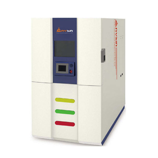
How the two architectures differ in practice
Envsin's three-zone configuration uses a fixed independent test zone plus a separate pre-heating zone and pre-cooling zone. The specimen stays where it is put; the thermal energy is moved to it. The design calls for a compressed air supply at 0.6–0.7 MPa, and the platform is listed against GJB 150.5-1986, MIL-STD-883H, MIL-STD-202G, IEC 60068-2-14, JIS C 60068-2-14, JASO D 014-4 and EIA JED-2531A.
Envsin's two-zone configuration is a movable-test-product design: pre-heat zone, pre-cool zone, and a specimen that travels between them in under 10 seconds. It is listed against GB/T 2423.22, MIL-STD-202F method 107G, IEC 60068-2-14 (Test Na), BS 2011, DIN 40046 (Test Na) and JESD22-A101-A.
| Specification | Three-zone Thermal Shock Test Chamber (500L) | Two-zone Thermal Shock Test Chamber (200L) |
|---|---|---|
| Test volume | 500 L | 200 L |
| Working chamber (W×D×H) | 900 × 800 × 700 mm | 600 × 550 × 600 mm |
| System architecture | Fixed independent test zone plus pre-heat and pre-cool zones | Movable test product, two-zone structure with pre-heat and pre-cool zones |
| Low-temperature shock range | −65 °C to −10 °C | −55 °C to −10 °C |
| High-temperature shock range | +60 °C to +150 °C | +60 °C to +150 °C |
| Temperature recovery time | ≤5 min | ≤5 min |
| Temperature transfer time | Not separately specified | <10 s |
| Uniformity / fluctuation / deviation | ≤2 °C / ±0.5 °C / ±2 °C | ≤2 °C / ±0.5 °C / ±2 °C |
| Pre-heat zone | +50 °C to +200 °C; ambient → +200 °C in approx. 50 min | +50 °C to +200 °C; ambient → +200 °C in approx. 40 min |
| Pre-cool zone | −80 °C to +70 °C; ambient → −80 °C in approx. 80 min | −80 °C to +70 °C; ambient → −80 °C in approx. 80 min |
| Long-cycle defrosting | ≥700 hours | ≥700 hours |
| Cooling method | Water-cooled | Water-cooled (refrigeration unit) |
| Max system power / current | Approx. 75.5 kW / approx. 123.3 A | Approx. 61 kW / approx. 104 A |
| Compressed air supply | 0.6–0.7 MPa | 0.6–0.7 MPa |
| Overall dimensions (W×D×H) | Approx. 1950 × 2350 × 2400 mm | Approx. 1270 × 2680 × 2320 mm |
| Listed standards | GJB 150.5-1986, MIL-STD-883H, MIL-STD-202G, IEC 60068-2-14, JIS C 60068-2-14, JASO D 014-4, EIA JED-2531A | GB/T 2423.22, MIL-STD-202F method 107G, IEC 60068-2-14 (Test Na), BS 2011, DIN 40046 (Test Na), JESD22-A101-A |
Both platforms share a 32-bit colour screen controller, Ethernet and USB data access, network video monitoring, APP remote management, automatic room-temperature recovery after test, maintenance reminders and remote service support. The functional difference that shapes daily use is the specimen interface. A fixed test zone keeps a cabled assembly stationary, which simplifies continuous instrumentation and in-test monitoring. A movable basket requires the cabling to travel with the load, so harness strain relief and connector choice become part of the test fixture design rather than an afterthought.
Application fit: materials science, communication, automotive
Materials science. Coupon-level work is characterised by many small specimens, short programmes and frequent reloading — the profile where the defrost interval binds first. The 200 L two-zone unit, with its GB/T 2423.22, IEC 60068-2-14 (Test Na) and JESD22-A101-A listings, is matched to that pattern; the 50 L thermal stress platform is the further step down for very small or very valuable samples. Where samples are wetted, coated or outgassing, the moisture caveat on defrost interval applies directly.
Communication. RF front ends, optical modules and base-station components are typically tested energised and monitored continuously. A fixed three-zone test zone keeps both the device and its harness still, and the four-channel load power supply control plus anti-condensation and over-temperature/smoke protection supports the monitoring arrangement. MIL-STD-202G, MIL-STD-883H and EIA JED-2531A listings on the 500 L platform align with that sector's qualification practice.
Automotive components. Connectors, sensors, ECUs and battery-adjacent parts sit between the two profiles. The 500 L three-zone platform lists JASO D 014-4 alongside the MIL-STD references, while the 200 L unit lists MIL-STD-202F method 107G and BS 2011. For battery-related programmes, the regulatory backdrop has tightened: China's GB 38031-2025 (Electric Vehicles Traction Battery Safety Requirements) took effect on 1 July 2026 and mandates a two-hour no-fire/no-explosion requirement, which increases the value of documented cycling evidence rather than anecdotal results.
Market context: what the installed base is responding to
Demand-side data gives the throughput question a commercial frame. The global environmental test chamber market was valued at USD 1.01 billion in 2025, according to Grand View Research, with hardware accounting for 83.3% of the product segment. The same source projects a 3.2% CAGR from 2026 to 2033 — modest growth that points to replacement and capability upgrades rather than pure volume expansion.
Regional weight sits in Asia Pacific, which held a 38.7% revenue share in 2025, and the largest single end-market is aerospace and defence at 30.6% of demand in 2025. For buyers, that combination has two practical implications: lead times and service response in Asia-based supply chains matter more than they did a decade ago, and the specification conversation increasingly happens against aerospace-grade documentation expectations rather than general industrial ones.
Envsin's own profile fits that picture — 70% export ratio, 18 service centres across 16 countries, and a stated market list spanning the United States, Germany, Poland, South Korea, Russia, Malaysia, Turkey, Vietnam, Mexico, Italy, Canada, the United Kingdom, Israel and Ukraine.
Where a thermal shock chamber is the wrong answer
A thermal shock chamber is not automatically the correct tool, and the comparison with adjacent solutions is worth making before a specification is fixed.
Against single-chamber ramping. Where the applicable standard permits a controlled ramp rather than a defined transfer, a rapid temperature change chamber avoids the shock chamber's infrastructure burden. Envsin's 990 L rapid temperature change humidity chamber, for example, offers heating and cooling rates of 15 °C/min linear within −55 °C to +125 °C with adjustable rates from 3 to 30 °C/min. It uses one working volume instead of three, which simplifies fixturing. The trade-off is that a ramp is not a transfer: air-to-air shock produces a step change that a ramp cannot reproduce, so standards built around transfer events still require a shock platform.
Against liquid-to-liquid shock. Envsin's liquid bath platforms (EYC603S2 at 2.6 L, EYC605S2 at 4.5 L) achieve recovery under 5 minutes and transfer under 10 seconds through fluorocarbon oil immersion, with temperature ranges of +70 °C to +150 °C on the hot side and −65 °C to 0 °C on the cold side. Media-based heat transfer is fast and uniform for small parts such as BGA components and bare dies, but 2.6 litres of specimen basket volume excludes most assemblies outright. The choice is driven by specimen size long before it is driven by performance.
The real constraints of the two platforms compared here. Both are water-cooled machines requiring a three-phase 380 V supply with grounding resistance below 4 Ω and a compressed air supply at 0.6–0.7 MPa — site services that a benchtop evaluation will not reveal. The 500 L three-zone unit draws approximately 75.5 kW at roughly 123.3 A and occupies around 1950 × 2350 × 2400 mm; the 200 L two-zone unit draws approximately 61 kW at roughly 104 A across 1270 × 2680 × 2320 mm. Neither footprint is small, and the 500 L platform in particular needs a floor plan and an electrical study completed before the purchase order rather than after.
There is a second boundary worth stating plainly: for the 500 L and 200 L platforms, no maximum specimen heat-dissipation figure is published in the product data used here. Only the 50 L thermal stress platform states a recommendation (below 300 W, with customised solutions for higher demands). A buyer planning to test powered loads on the larger units should obtain that figure in writing rather than infer it from the smaller model.
Future outlook
Two directions look durable. The first is evidence quality: as battery and automotive safety rules tighten — GB 38031-2025 is the clearest current example — a thermal shock result becomes a document that has to survive audit, not just a pass/fail line in a lab notebook. That favours chambers with native data logging, Ethernet and USB access, and traceable controller records over retrofit instrumentation.
The second is unattended operation. Remote management, network video monitoring, automatic room-temperature recovery and maintenance reminders are already standard functions on both platforms discussed here, and market analysis of the environmental test chamber category points to continued integration of automation and connectivity. Practically, this shifts the buyer's attention from the chamber alone to the chamber plus its service path. Envsin's stated support model is remote assistance plus on-site service through 18 global service centres, with all units subject to 100% pre-shipment testing and ISO/IEC calibration, and the manufacturer operates OEM, ODM and custom manufacturing with a one-unit minimum order and lead times of 30–45 days for standard configurations and 45–60 days for custom builds.
FAQ
What does a ≤5 minute temperature recovery time mean on a thermal shock chamber?
On the Envsin Three-zone Thermal Shock Test Chamber (500L), temperature recovery time is specified at ≤5 minutes. It is the interval in which the working volume returns inside its stated tolerance band after the specimen enters the test zone, against quoted figures of ≤2 °C uniformity, ±0.5 °C fluctuation and ±2 °C deviation. It is a chamber-level value and does not represent the time the specimen itself needs to reach the new temperature.
How is temperature transfer time different from recovery time?
Transfer time is the physical movement of the specimen between the hot and cold zones; recovery time is the period after arrival during which the working volume re-establishes its temperature band. The 200 L two-zone unit specifies transfer time <10 s and recovery ≤5 min. The 50 L thermal stress and 100 L stress-screening platforms specify the same pairing and note that recovery is measured at the air outlet. The 500 L three-zone unit specifies recovery ≤5 min without a separate transfer figure.
What is long-cycle defrosting at ≥700 hours, and why does it affect test volume?
During low-temperature operation, moisture freezes on the evaporator and reduces heat exchange, so the refrigeration system runs an automatic defrost sequence during which testing stops. Long-cycle defrosting at ≥700 hours specifies how far apart those interruptions are designed to occur. Both the 500 L three-zone and 200 L two-zone platforms list long-cycle defrosting at ≥700 hours. In high-frequency, short-programme workloads the interval becomes the binding limit on total test volume; the figure is a design specification, and moisture from door openings or wet specimens shortens the practical interval.
How many specimens fit in a 500 L three-zone chamber compared with a 200 L two-zone unit?
Working chambers measure 900 × 800 × 700 mm (500 L three-zone) and 600 × 550 × 600 mm (200 L two-zone). Usable capacity is lower than these envelopes because airflow clearance, fixturing and — on the movable two-zone design — basket travel space must be subtracted. Both platforms provide four-channel load power supply control, which caps simultaneously energised devices at four channels per chamber irrespective of physical capacity. A physical fit check with the actual fixture is more reliable than volume arithmetic.
Which platform suits materials science, communication or automotive component testing?
Materials science programmes using many small coupons fit the 200 L two-zone unit or the 50 L thermal stress platform, with listings against GB/T 2423.22, IEC 60068-2-14 (Test Na) and JESD22-A101-A. Communication modules tested energised benefit from the 500 L three-zone fixed test zone, which avoids moving cabled assemblies, under MIL-STD-202G, MIL-STD-883H and EIA JED-2531A. Automotive connectors, sensors and ECUs sit between the two; the 500 L unit additionally lists JASO D 014-4 and the 200 L unit lists MIL-STD-202F method 107G and BS 2011.
What site services do these thermal shock chambers require?
Both require AC380V ±10%, 50Hz ±1, three-phase four-wire supply with grounding, grounding resistance below 4 Ω, water cooling, and compressed air at 0.6–0.7 MPa with pneumatic air moisture ≤30 g/m³ (dry air ≤1.5 g/m³ optional). Maximum system power and current are approximately 75.5 kW and 123.3 A for the 500 L three-zone unit, and approximately 61 kW and 104 A for the 200 L two-zone unit.
How is a chamber validated before shipment and on arrival?
Envsin states 100% pre-shipment testing with ISO/IEC calibration across its manufacturing output. Procurement terms recorded for the range specify a one-unit minimum order, delivery terms including FOB, CIF, EXW and DDP, and acceptance criteria based on a pre-shipment factory acceptance test plus an on-site acceptance test with calibration certificate. Standard lead time is 30–45 days, extending to 45–60 days for custom configurations.
The short version
Three numbers decide how much thermal shock testing a laboratory can actually run: the recovery time that closes each cycle, the defrost interval that removes whole days from the calendar, and the usable volume inside the quoted litres. On Envsin's range, the 500 L three-zone platform competes on cycle density and specimen stability at ≤5 minutes recovery, while the 200 L two-zone platform competes on sustained short-run throughput, backed by a ≥700-hour defrosting interval and a 600 × 550 × 600 mm working chamber. Buyers who compare only temperature range and litres will still get a working chamber — they simply will not know, until month two, which of the three variables they actually bought.
For detailed specifications across the range, the Envsin product brochure is available for download: Envsin environmental test chamber brochure (PDF).
Tem questões ou precisa de mais detalhes?
Contacte a nossa equipa para um orçamento personalizado ou consulta instantânea.
Solicitar orçamento
Preencha o formulário abaixo e a nossa equipa entrará em contacto com uma proposta personalizada.
Chat direto do WhatsApp
Prefere conversar em tempo real? Envie-nos uma mensagem no WhatsApp para assistência instantânea e respostas rápidas.
- Obter orçamento personalizado
- Partilhar fotos ou documentos
- Discuta as suas necessidades diretamente
Geralmente responde em 5–30 minutos durante o horário de expediente.